Light source module of laser television and laser projection television

A light source module, laser TV technology, applied in optics, optical components, installation, etc., can solve the problem of high sealing cost and achieve the effect of reducing sealing cost

Active Publication Date: 2018-10-02
QINGDAO HISENSE LASER DISPLAY CO LTD
View PDF5 Cites 9 Cited by
  • Summary
  • Abstract
  • Description
  • Claims
  • Application Information

AI Technical Summary

Problems solved by technology

[0005] The embodiment of the present invention provides a light source module of a laser TV and a laser projection TV, which can solve the problem of high sealing cost caused by the overall airtight sealing of the existing light source module

Method used


Image

  • Light source module of laser television and laser projection television
  • Light source module of laser television and laser projection television
  • Light source module of laser television and laser projection television

Examples


Embodiment 1

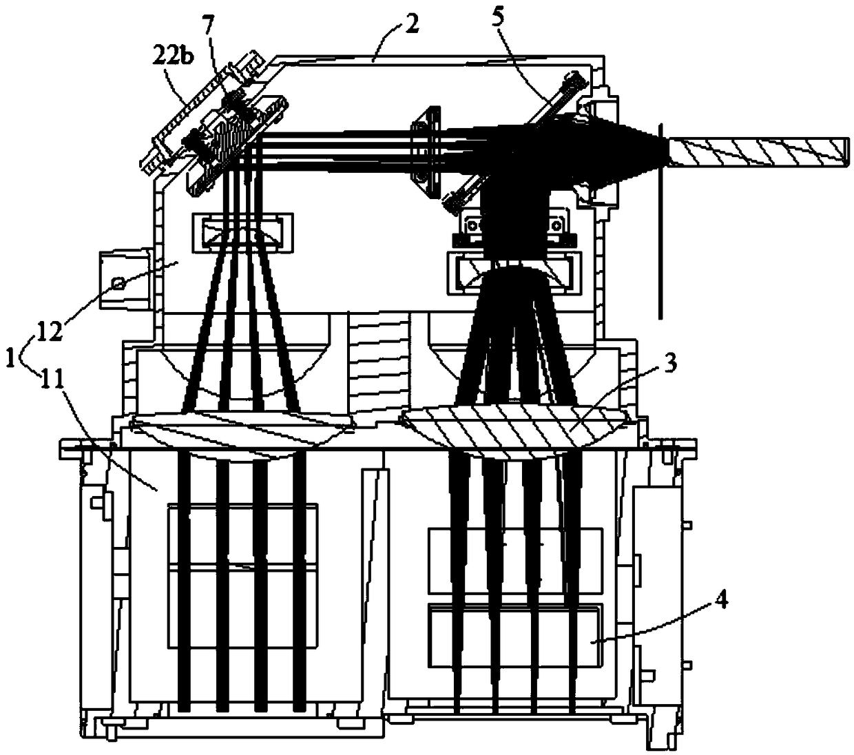
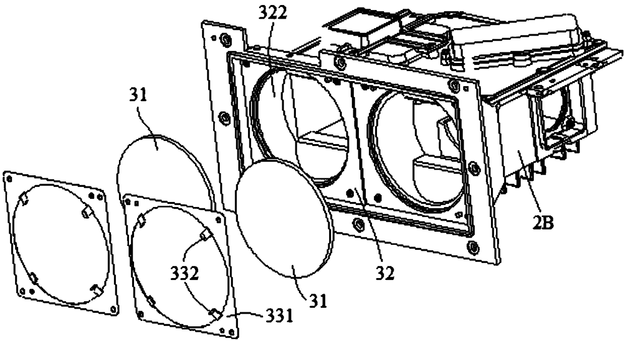
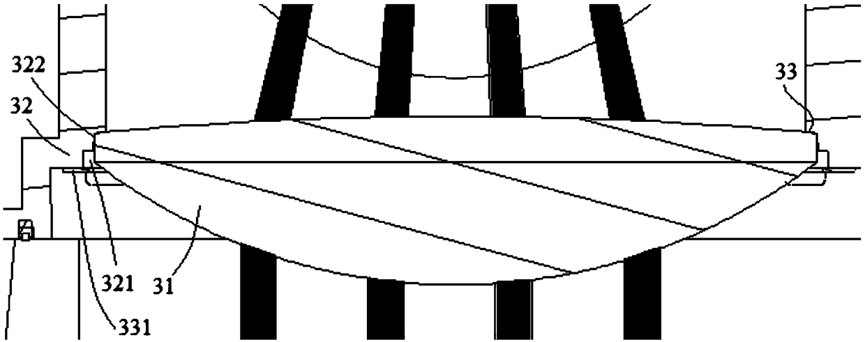
[0027] figure 1 and figure 2 It is a specific embodiment of the light source module of the laser TV in the embodiment of the present invention. The light source module of the laser TV in this embodiment includes a housing 2 with a cavity 1 inside, and a partition structure 3 is provided in the cavity 1 to separate The structure 3 divides the cavity 1 into a first chamber 11 and a second chamber 12 that are not connected to each other. The light source module also includes a laser component 4 and an optical lens component. The optical lens component includes a first light-transmitting optical lens 31 and is arranged on The second optical lens assembly 5 in the output light path of the first light-transmitting optical lens 31; the separation structure 3 includes the first light-transmitting optical lens 31 and the support portion 32 for supporting the first light-transmitting optical lens 31, the first chamber 11 A laser assembly 4 is installed, and the second chamber 12 is in...

Embodiment 2

[0048] The following will take a three-color laser light source as an example for description. Laser assembly 4 comprises blue laser, red laser, green laser; The number is the same as the number of the laser beams; when there are multiple first light-transmitting optical lenses 31 , the second optical lens assembly 5 of the second chamber 12 at least includes light-combining lenses.

[0049] In a specific embodiment of the present invention, refer to figure 1 , Figure 6 and Figure 7 :

[0050] The laser assembly 4 includes a red laser module 41 (comprising a plurality of lasers), a green laser module 42, a blue laser module 43, a first light combining mirror 44 (a dichroic mirror or a reflector group arranged at intervals) and a second Two light-combining mirrors 45 (X-combining mirrors); the first part 2A includes a left half and a right half (these two parts are integrally formed), the top surface and the side of the left half are respectively provided with a green las...

Embodiment 3

[0058] refer to Figure 10 , the embodiment of the present invention also provides a laser projection television, including a laser light source 10, an optical machine 20, and a lens 30. The laser light source 10 provides illumination for the optical machine 20, and the optical machine 20 modulates the light beam of the light source and outputs it to the lens 30. Imaging is performed and projected onto the projection medium 40 to form a projection screen. The laser light source 10 is the light source module described in any one of the above technical solutions.

[0059]In the laser projection TV provided by the embodiment of the present invention, since the light source module includes a housing 2 with a cavity 1 inside, the cavity 1 is provided with a partition structure 3, and the partition structure 3 divides the cavity 1 into first, non-connected The chamber 11 and the second chamber 12, the light source module also includes a laser assembly 4 and an optical lens assembly,...


PUM


Abstract

The invention discloses a light source module of a laser television and a laser projection television, and relates to the technical field of the laser television. By the light source module, the problem of excessively high sealing cost caused by the adoption of airtight-level sealing of the whole light source module is solved. The light source module of the laser television comprises a shell, wherein a cavity is formed in the shell, a partition structure is arranged in the cavity and is used for dividing the cavity to a first chamber and a second chamber which do not communicate with each other, the light source module also comprises a laser module and an optical lens module, the optical lens module comprises a first transmitting optical lens and a second optical lens module, the second optical lens module is arranged in an output light path of the first transmitting optical lens, the partition structure comprises the first transmitting optical lens and a support part, the support partis used for supporting the first transmitting optical lens, the laser module is arranged in the first chamber, and the second optical lens module is arranged in the second chamber. The light source module is used for the laser television.

Description

technical field [0001] The invention relates to the technical field of laser televisions, in particular to a light source module of a laser television and a laser projection television. Background technique [0002] At present, laser TV is mainly composed of optical engine, heat dissipation system, and circuit control system; its core component is the optical engine. The optical engine part is composed of a light source part and an optical machine part. The function of the light source part is to provide illumination for the light machine, and the function of the light machine part is to modulate the illumination beam provided by the light source, and finally form a projection image through the lens. [0003] The above-mentioned light source part specifically includes a housing, a laser component, and an optical lens component. The light beam emitted by the laser component is shaped and combined by the optical lens component, thereby providing illumination for the optical ma...

Claims


Application Information

Patent Timeline
Patent Type & Authority Applications(China)
IPC IPC(8): G03B21/20G02B7/02
CPCG02B7/02G02B7/025G03B21/2013G03B21/2033G03B21/20
Inventor 李建军
Owner QINGDAO HISENSE LASER DISPLAY CO LTD
Why Eureka
Try Eureka