Device for cleaning brake disc

A technology for cleaning devices and brake discs, applied to cleaning methods and tools, cleaning methods using tools, and drying solid materials without heating, etc., can solve the problems of time-consuming cleaning of brake discs, safety accidents affecting brake performance, etc. problems, to achieve the effect of improving cleaning efficiency, shortening cleaning time and reducing waste

Active Publication Date: 2018-10-09
CHONGQING IND POLYTECHNIC COLLEGE
View PDF8 Cites 6 Cited by
  • Summary
  • Abstract
  • Description
  • Claims
  • Application Information

AI Technical Summary

Problems solved by technology

[0003] However, since the brake disc is installed on the inner side of the wheel of the car, the car will splash dust and some other stains during driving, so it is extremely easy to dirty the brake disc
Stains on the brake disc will lead to insufficient friction between the brake disc and the brake pad when the car is braking, which will affect the effectiveness of the brake and even cause the brake to fail, resulting in safety accidents
[0004] At present, most people clean the brake discs manually, but manual cleaning cannot guarantee that the brake discs can be cleaned, and after the brake discs are cleaned, they need to be dried with a towel, which takes a long time , so there is an urgent need for a mechanized device for quickly cleaning the brake disc

Method used


Image

  • Device for cleaning brake disc
  • Device for cleaning brake disc
  • Device for cleaning brake disc

Examples


Embodiment 1

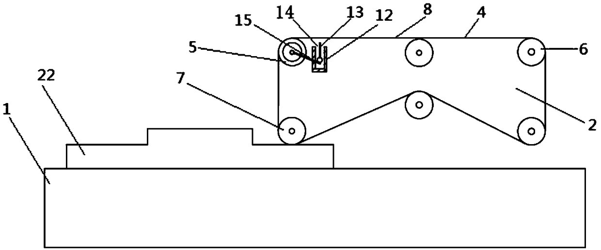
[0031] This embodiment is basically as figure 1 Shown: a brake disc cleaning device, including a support base 1, a cleaning part 2 and a power unit, and the power unit is set as a drive motor. The cleaning unit 2 is provided with a rotating belt 4, a conveying roller 5, a rotating roller 6 and a pressure roller 7, the rotating belt 4 is wound on the conveying roller 5, the rotating roller 6 and the pressing roller 7, and the power unit drives the rotating roller 6 to rotate.

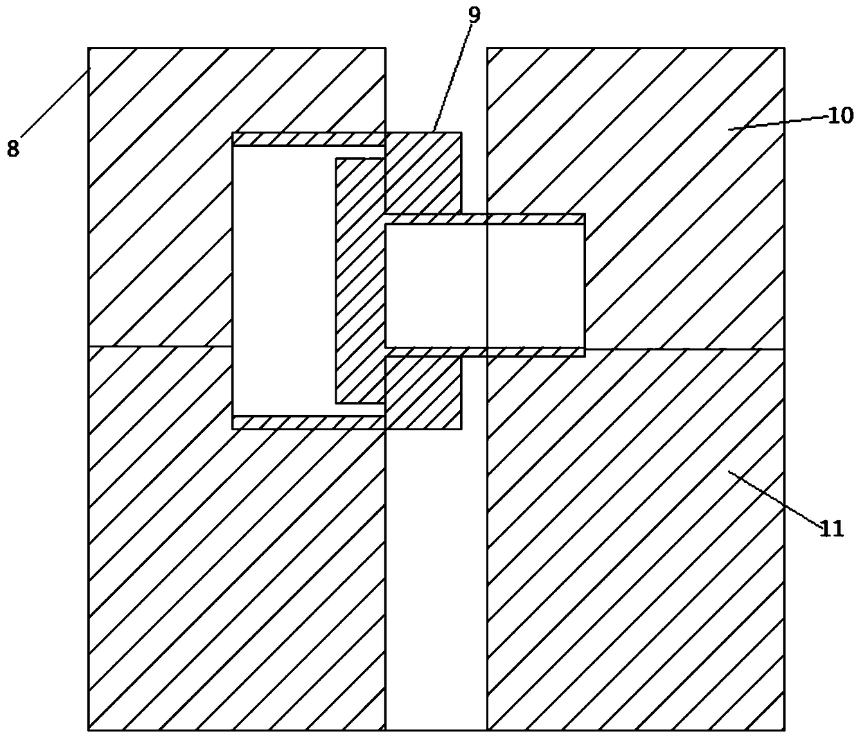
[0032] Rotating belt 4 comprises some cleaning belts 8 and rotating shaft 9, as figure 2 , 5 As shown, the adjacent cleaning belts 8 are hinged end to end through the rotating shaft 9, and the cleaning belts 8 are evenly divided into upper and lower layers with different materials. The upper water-absorbing layer 10 is set to be made of cotton material, the cleaning layer 11 is set to be made of rubber material, and the rotating shaft 9 is set in one layer of cotton material.

[0033] The cleaning se...

Embodiment 2

[0037] Such as Figure 6 As shown, the brake disc cleaning device, the difference between this embodiment and the above embodiments is that: the support base 1 is provided with a rotating unit for driving the brake disc 22 to rotate, and the rotating unit in this embodiment is the rotating shaft 21 . Such as Figure 9 As shown, the pressing roller 7 is provided with a protrusion for pushing out the cleaning belt 8 for pushing out the cleaning belt 8 . Such as Figure 8 As shown, the conveying roller 5 is provided with a groove for placing the cleaning belt 8, and the cleaning belt 8 is positioned in the groove during device operation.

[0038] During specific implementation, the rotating shaft 21 is powered by the driving motor to rotate, so that the brake disc 22 rotates, which facilitates the cleaning part 2 to clean the brake disc 22, can clean the brake disc 22 more fully, and improves cleaning efficiency. In addition, a protrusion is provided on the pressure roller 7 ,...

Embodiment 3

[0040] Such as Figure 7 As shown, the brake disc cleaning device, the difference between this embodiment and the second embodiment is that: the support base 1 is provided with a water tank 17 for cleaning the cleaning belt 8, and the water tank 17 is provided with a cleaning roller 18 for cleaning the cleaning belt 8, and the cleaning roller 18 is connected with conveying roller 5 by gear 19, toothed chain 20.

[0041] During specific implementation, the drive motor is started, and the drive motor drives the rotating roller 6 to start rotating. The turning roller 6 is connected with other parts of the cleaning unit 2 through the turning belt 4, so the turning roller 6 drives the whole cleaning unit 2 to start running. When the cleaning belt 8 passes through the pressure roller 7 and moves toward the water tank 17, the cleaning belt 8 is in a relaxed state at this time. Due to gravity, the rubber side of the cleaning belt 8 faces downward and is on the outside of the cleaning...


PUM


Abstract

The invention belongs to the technical field of automobile auxiliary equipment, in particular to a device for cleaning a brake disc. The device comprises a support base, a cleaning part and a power unit, wherein the cleaning part is provided with a rotating belt, a conveying roller, a rotating roller and resisting and pressing rollers; the rotating belt is wound on the conveying roller, the rotating roller and the resisting and pressing rollers; the rotation roller is driven by the power unit to be rotated; the rotation belt comprises a plurality of cleaning belts and a rotating shaft which ishinged to the head parts and the tail parts of the cleaning belts; the cleaning belts are divided into upper layers and lower layers made of different materials; the upper layers and the lower layersare respectively water absorption layers and cleaning layers; the cleaning part also comprises a turning mechanism which is used for turning the cleaning belts; the turning mechanism comprises a turning rod, a sliding slot for guiding the turning rod and a stirring rod which is connected with the end surface of the conveying roller; and a plurality of brace rods for turning the cleaning belts arearranged on the turning rod. By adopting the technical scheme, the requirements on mechanical cleaning and drying-up of the brake disc can be met, and traffic accidents caused by brake failure due tostains formed in the brake disc are avoided.

Description

technical field [0001] The invention belongs to the technical field of cleaning devices, and in particular relates to a brake disc cleaning device. Background technique [0002] The types of brakes mainly include disc brakes, drum brakes and air brakes. Most of the older cars have brake configurations with front discs and rear drums. With the continuous development of science and technology, people's safety awareness has gradually increased. Many cars now have front and rear brakes configured as disc brakes. Compared with drum brakes, disc brakes have better heat dissipation, and are not prone to thermal fading under high-speed braking conditions, so their high-speed braking effects are also better. [0003] However, since the brake disc is installed on the inside of the wheel of the car, the car will splash dust and some other stains during driving, so it is extremely easy to dirty the brake disc. Stains on the brake disc will lead to insufficient friction between the bra...

Claims


Application Information

Patent Timeline
Patent Type & Authority Applications(China)
IPC IPC(8): B08B1/02F26B5/14
CPCB08B1/001B08B1/007F26B5/14
Inventor 俞燕陈冬欧阳刚苏姝苏涛欧阳桦
Owner CHONGQING IND POLYTECHNIC COLLEGE
Why Eureka
Try Eureka