Visual inertial range measurement method and equipment using online time calibration

A technology of time calibration and odometry, which is applied in image data processing, instruments, calculations, etc., and can solve problems such as moving speed errors

Active Publication Date: 2018-10-09
INST OF AUTOMATION CHINESE ACAD OF SCI
View PDF7 Cites 44 Cited by
  • Summary
  • Abstract
  • Description
  • Claims
  • Application Information

AI Technical Summary

Problems solved by technology

However, the frequency of image acquisition is significantly lower than the frequency of IMU measurement values. T

Method used


Image

  • Visual inertial range measurement method and equipment using online time calibration
  • Visual inertial range measurement method and equipment using online time calibration
  • Visual inertial range measurement method and equipment using online time calibration

Examples


Embodiment Construction

[0116] Preferred embodiments of the present invention are described below with reference to the accompanying drawings. Those skilled in the art should understand that these embodiments are only used to explain the technical principle of the present invention, and are not intended to limit the protection scope of the present invention.

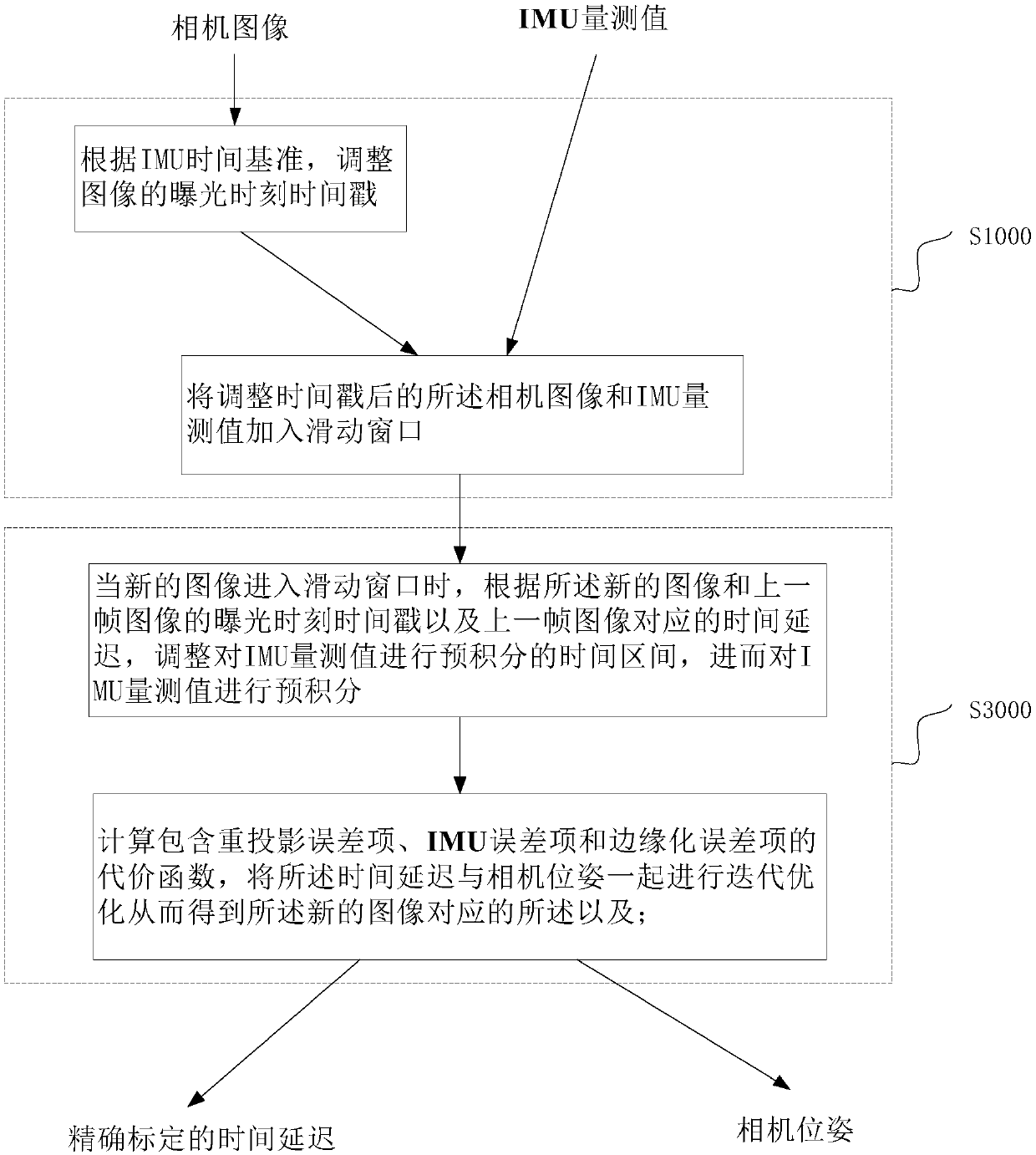
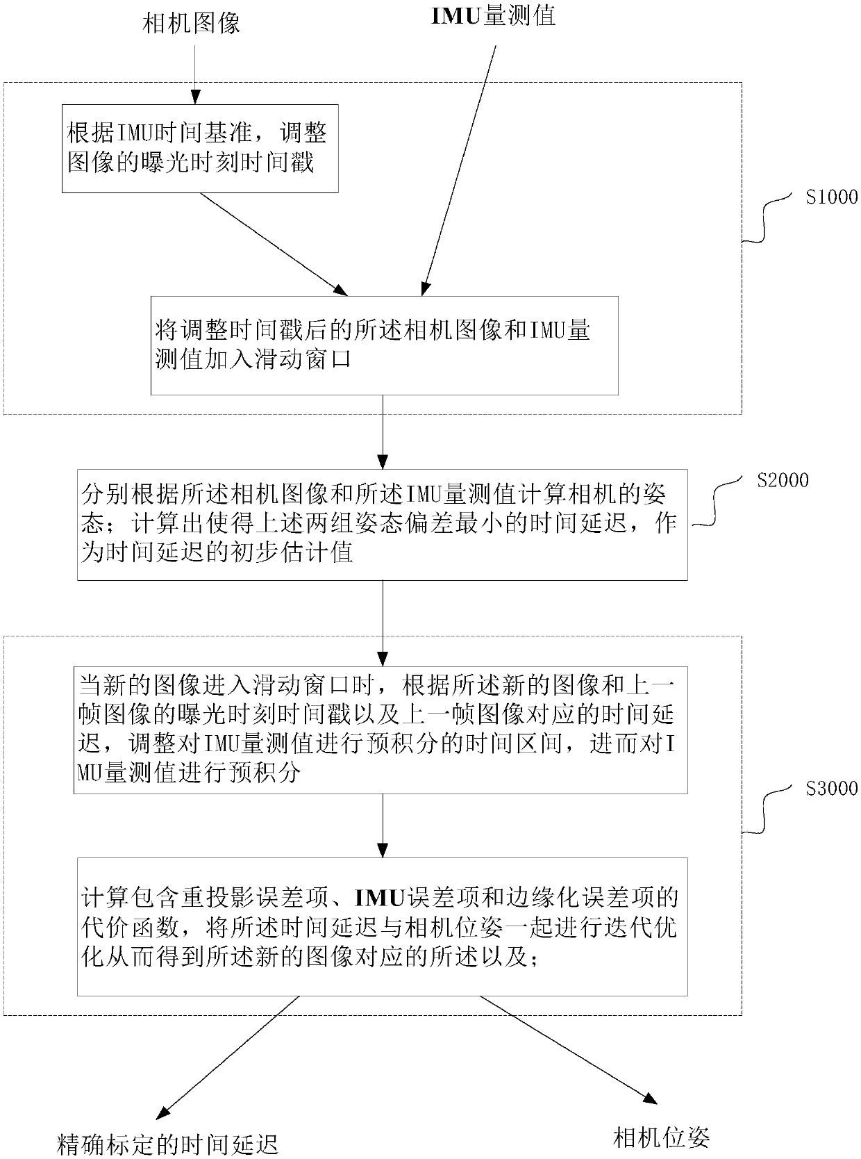
[0117] The invention proposes a visual inertial odometry method using online time calibration, and effectively improves the accuracy of camera tracking through online accurate calibration of the time delay of the camera and IMU system. The present invention is used to realize online calibration of time delay in VIO algorithms based on nonlinear optimization, such as VINS; these algorithms first use the IMU measurement value to perform pre-integration, and then in the local sliding window, the cost function is obtained by nonlinear optimization The real-time pose of the camera; the cost function includes a reprojection error term, an IMU error t...


PUM


Abstract

The invention relates to the multi-sensor time calibration algorithm field, especially relates to a visual inertial range measurement method and equipment using online time calibration and aims at increasing camera pose calculation precision. The visual inertial range measurement method comprises the following steps of roughly aligning the timestamp of a camera image with the time system of an IMUand taking the data of a camera and the IMU as input; taking the time delay closest to a camera pose calculated by the camera data and the IMU data as the preliminary estimation value of camera timedelay; and using an IMU error item expression method with a time delay parameter to add a correction term related to the time delay into the pre-integration result of the IMU, taking as the parameterof nonlinear optimization and realizing the accurate calibration of the time delay. Compared with an existing method, by using the method of the invention, time delay calibration is accurate, and forequipment which does not carry out hardware synchronization, better performance can be achieved when the equipment rapidly makes a turn and suddenly stops.

Description

technical field [0001] The invention relates to the field of multi-sensor time calibration algorithms, in particular to a visual inertia odometry method and equipment using online time calibration. Background technique [0002] Visual-inertial odometry using cameras and IMUs (inertial measurement units) has achieved good results in recent years because the information from vision and IMUs have complementary characteristics. In the early days, the MSCKF algorithm used the Extended Kalman Filter (EKF) to achieve camera tracking, followed by OKVIS and VINS using nonlinear optimization, and a version of the ORB-SLAM algorithm using vision and IMU information. These algorithms are widely used in MAV localization and augmented reality. These algorithms all assume that the time stamps of the camera and IMU are synchronized, but the camera and IMU are not synchronized by hardware on Android phones, and the time stamp of the camera has a time delay relative to its exposure time. Be...

Claims


Application Information

Patent Timeline
IPC IPC(8): G06T7/277G06T7/70G06T7/80
CPCG06T7/277G06T7/70G06T7/80G06T2207/10004
Inventor 刘津旭高伟胡占义
Owner INST OF AUTOMATION CHINESE ACAD OF SCI
Why Eureka
Try Eureka