Passive containment heat exchanger system
A passive containment and heat exchanger technology, applied in the field of nuclear reactors, can solve the problems of large deformation, poor anti-seismic performance, and low heat exchange efficiency of air coolers and built-in heat exchangers, and achieve enhanced installation firmness and improved anti-seismic performance , Increase the effect of heat transfer capacity
- Summary
- Abstract
- Description
- Claims
- Application Information
AI Technical Summary
Problems solved by technology
Method used
Image

Examples
Embodiment 1
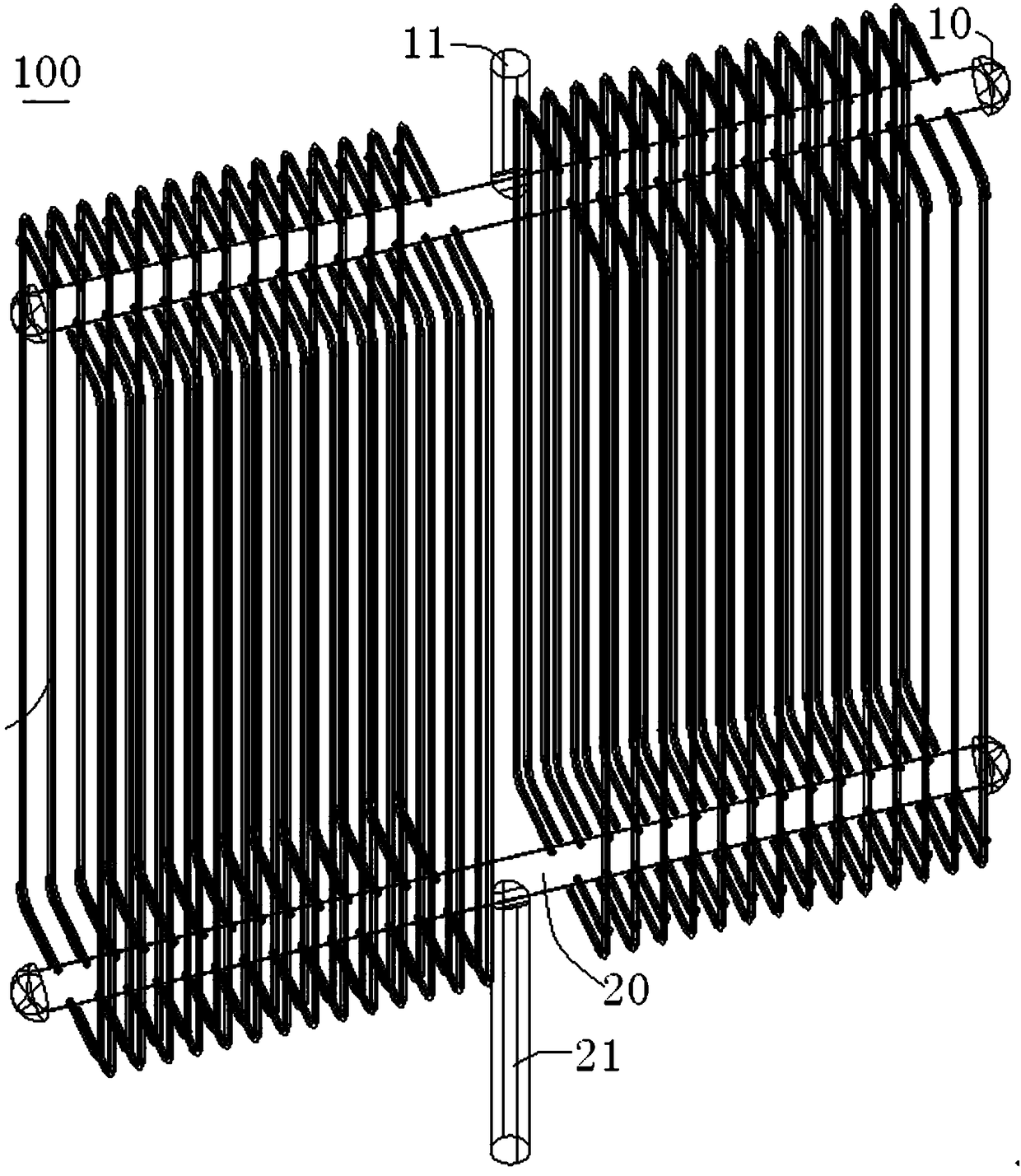
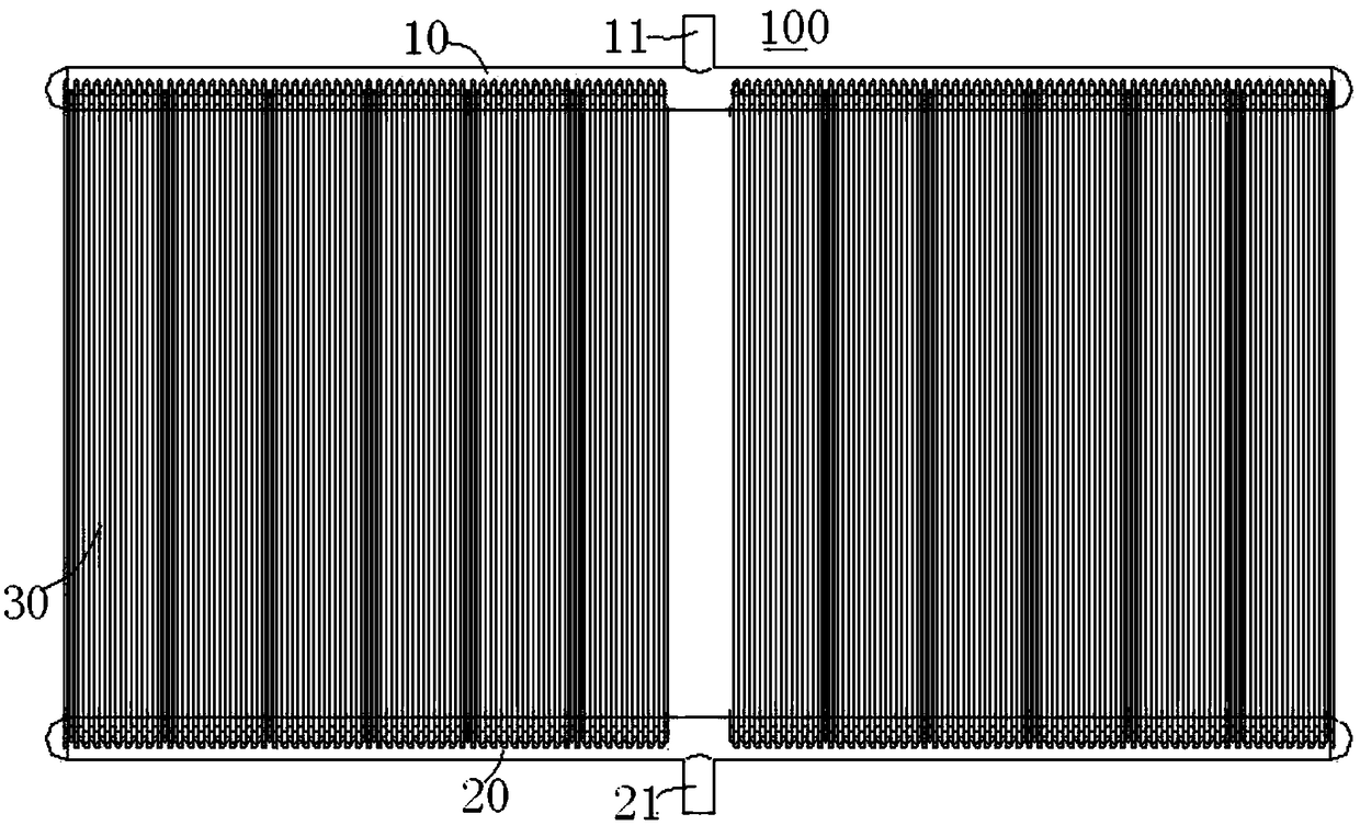
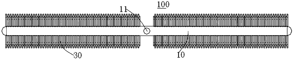
[0116] The built-in upper header 10 is formed as a straight pipe extending in the horizontal direction, and the built-in lower header 20 is also formed as a straight pipe extending in the horizontal direction. The heat exchanger outlet 11 is located on the middle upper side of the built-in upper header 10, that is, the built-in heat exchanger inlet 21 and the built-in heat exchanger outlet 11 are coaxially arranged and the openings are facing oppositely, that is, the built-in heat exchanger inlet 21 is at the bottom of the built-in lower header 20. The lower side opening is downward, the outlet 11 of the built-in heat exchanger is opened upward on the upper side of the built-in upper header 10, and the exhaust pipes 30 are respectively arranged on both sides of the built-in upper header 10 and the built-in lower The upper header 10 and the built-in lower header 20 are arranged symmetrically on both sides in the length direction.
[0117] The fluid can enter the built-in lower ...
Embodiment 2
[0119]The built-in upper header 10 is formed as a straight pipe extending in the horizontal direction. The built-in lower header 20 is mainly composed of a first straight pipe section 22 and two second straight pipe sections 23. The first straight pipe section 22 is located between the two second straight pipe sections. 23, both ends of the first straight pipe section 22 are respectively connected with two second straight pipe sections 23, the two second straight pipe sections 23 are spaced apart, and the built-in heat exchanger inlet 21 is located in the first straight pipe section of the built-in lower header 20 22, the outlet 11 of the built-in heat exchanger is located on the upper side of the middle of the built-in upper header 10, that is, the inlet 21 of the built-in heat exchanger and the outlet 11 of the built-in heat exchanger are arranged coaxially and have the same opening orientation, that is, the outlet of the built-in heat exchanger The inlet 21 opens upward on t...
Embodiment 3
[0122] The built-in upper header 10 and the built-in lower header 20 are respectively formed as circular tubes of the same size. The built-in heat exchanger 100 includes a built-in heat exchanger inlet 21 and a built-in heat exchanger outlet 11. The built-in heat exchanger inlet 21 is located in the built-in heat exchanger. On the outside of the lower header 20, the built-in heat exchanger outlet 11 is located outside the built-in upper header 10, and the built-in heat exchanger inlet 21 and the built-in heat exchanger outlet 11 are at the same position on the built-in lower header 20 and the built-in upper header 10 , the upper end of the row pipe 30 is bent inwardly and connected to the built-in upper header 10, the lower end of the row pipe 30 is bent inwardly and connected to the built-in lower header 20, and the row pipe 30 is along the built-in upper header 10 and the built-in lower header The circumferential distribution of 20 is arranged in a cylindrical shape.
[0123...
PUM
 Abstract
Description
Claims
Application Information
 - R&D
- Intellectual Property
- Life Sciences
- Materials
- Tech Scout
- Unparalleled Data Quality
- Higher Quality Content
- 60% Fewer Hallucinations
Browse by: Latest US Patents, China's latest patents, Technical Efficacy Thesaurus, Application Domain, Technology Topic, Popular Technical Reports.
© 2025 PatSnap. All rights reserved.Legal|Privacy policy|Modern Slavery Act Transparency Statement|Sitemap|About US| Contact US: help@patsnap.com