Self-locking device for switch cabinet valve mechanism, and switch cabinet

A technology of self-locking device and switchgear, which is applied in the direction of switchgear, pull-out switchgear, electrical components, etc., can solve the problems of high safety risks for workers, and achieve the effect of simple manufacture

Pending Publication Date: 2018-10-09
SIEMENS SWITCHGEAR LTD SHANGHAI
View PDF0 Cites 1 Cited by
  • Summary
  • Abstract
  • Description
  • Claims
  • Application Information

AI Technical Summary

Problems solved by technology

There is a high risk to the safety of workers when this approach is implemented

Method used


Image

  • Self-locking device for switch cabinet valve mechanism, and switch cabinet
  • Self-locking device for switch cabinet valve mechanism, and switch cabinet
  • Self-locking device for switch cabinet valve mechanism, and switch cabinet

Examples


Embodiment Construction

[0044] In order to have a clearer understanding of the technical features, purposes and effects of the invention, the specific embodiments of the present invention will now be described with reference to the accompanying drawings. In each figure, the same reference numerals represent components with the same structure or similar structure but the same function.

[0045] In this article, "schematic" means "serving as an example, example or illustration", and any illustration or implementation described as "schematic" in this article should not be interpreted as a more preferred or more advantageous Technical solutions.

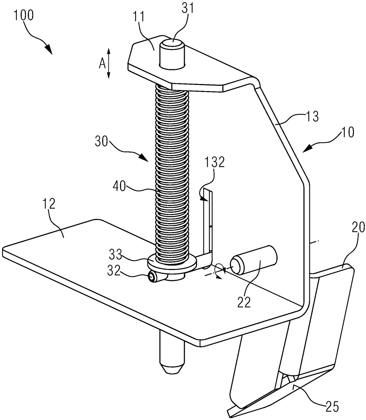
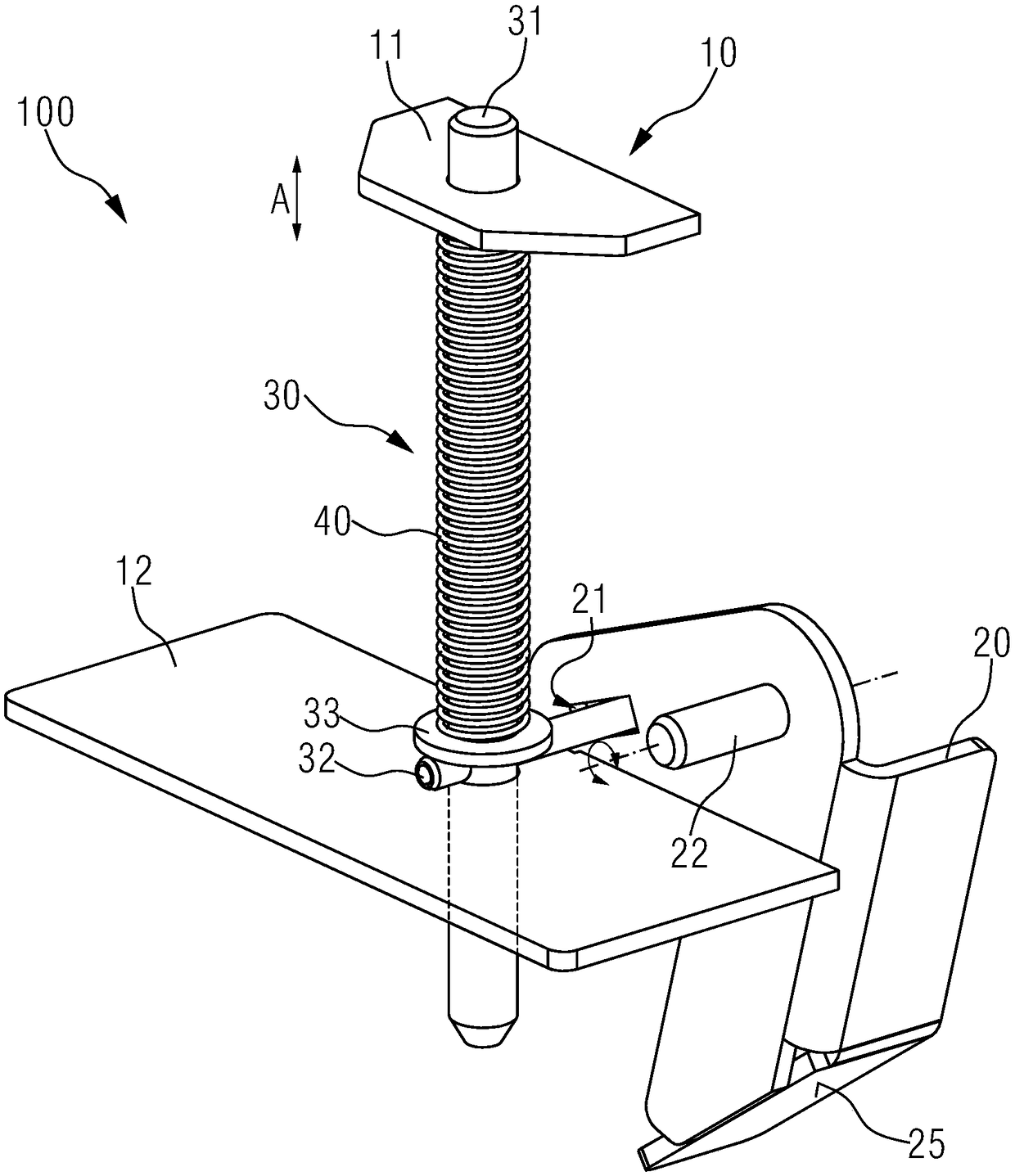
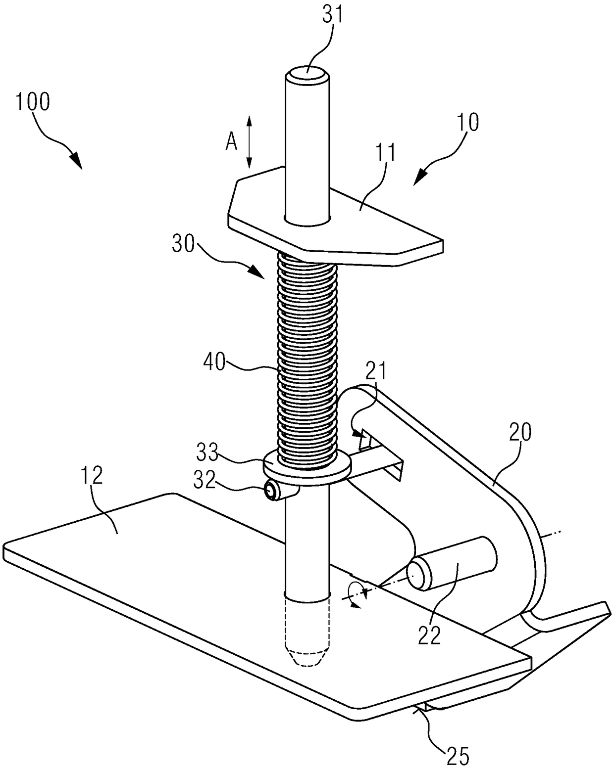
[0046] figure 1 with figure 2 It is a schematic structural diagram of a schematic embodiment of a self-locking device for a switch cabinet valve mechanism. For clarity, figure 2 Some structures are omitted. Such as figure 1 with figure 2 As shown, the self-locking device 100 includes a support frame 10 , a rotating member 20 , a limiting assembly 30 and...


PUM


Abstract

The invention provides a self-locking device for a switch cabinet valve mechanism. The self-locking device comprises a supporting frame (10), a rotating piece (20), a limiting assembly (30), and a reset spring (40). The rotating piece is rotatably connected to the supporting frame. The limiting assembly is slidably connected with the supporting frame, the limiting assembly is used for locking or unlocking a closing state of the valve mechanism by sliding. One end of the reset spring is used for applying force to the limiting assembly, and the other end of the reset spring is used for applyingforce to the supporting frame. The rotating piece can slide in the direction of unlocking the closing state relative to the supporting frame by rotating the abutting-resisting the limiting assembly, so that the reset spring can store energy, the energy-storage reset spring is used for applying force to the limiting assembly to enable the limiting assembly to slide in the direction of locking the closed state. The self-locking device can automatically unlock the closing state of the valve mechanism when the handcart is pushed into the cabinet body; and the closing state of the valve mechanism is automatically locked after the handcart is moved out of the cabinet body. In addition, the invention further provides a switch cabinet comprising the self-locking device.

Description

technical field [0001] The invention relates to a locking device for a valve mechanism of a switch cabinet, in particular to a self-locking device capable of automatically locking the valve mechanism of a switch cabinet after the handcart is moved out, and a switch cabinet including the same. Background technique [0002] In the removable switch cabinet, the handcart is connected to the static contact fixedly installed in the cabinet through the moving contact of the contact arm system, which ensures the continuity of the main power distribution circuit. During use, the moving contact of the handcart and the static contact of the cabinet are connected or disconnected by pushing in or removing the handcart. Static contacts are usually connected to live parts of the power distribution system. Usually, a valve mechanism is set between the handcart and the static contact in the cabinet, and the valve mechanism can reach the closed state after the handcart moves out of the cabin...

Claims


Application Information

Patent Timeline
Patent Type & Authority Applications(China)
IPC IPC(8): H02B11/133
CPCH02B11/133
Inventor 邱正平邹信用王健峰翟保安
Owner SIEMENS SWITCHGEAR LTD SHANGHAI
Why Eureka
Try Eureka