A motor rotor position detection method and detection device

A technology for motor rotors and detection methods, applied to measuring devices, using electrical devices, using electromagnetic means, etc., can solve the problems of low frequency selectivity between AC excitation excitation signals and detection signals, and achieve flexible and diverse spatial arrangements and anti-interference Strong performance and good fault tolerance

Active Publication Date: 2021-05-11
TONGJI UNIV
View PDF7 Cites 1 Cited by
  • Summary
  • Abstract
  • Description
  • Claims
  • Application Information

AI Technical Summary

Problems solved by technology

[0005] 1) The frequency selectivity of AC excitation excitation signal and detection signal is not strong, and it is easy to be interfered by harmonics;

Method used


Image

  • A motor rotor position detection method and detection device
  • A motor rotor position detection method and detection device
  • A motor rotor position detection method and detection device

Examples


Embodiment 1

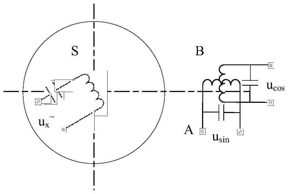
[0031] Such as image 3 As shown, in this embodiment, one primary side is set to establish the excitation magnetic field, and the two secondary sides are arranged orthogonally. The primary side and the secondary side are coupled by air and have no iron core. The mutual inductance between sides varies with the rotor position in a sine and cosine manner, respectively.

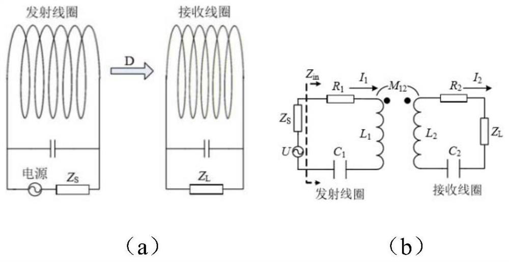
[0032] The compensation circuits of the primary side and the secondary side are designed as series compensation, and the resonant frequencies of the primary side and the secondary side are designed to be equal, calculated as:

[0033]

[0034] Among them, L is the self-inductance of the coil, C is the capacitance of the series compensation circuit, and the loop impedance is the internal resistance R of the coil at this time.

[0035] Apply an AC simple harmonic excitation voltage U with a constant amplitude to both ends of the primary circuit x , and keep U x The frequency f is equal to the resonant frequen...

Embodiment 2

[0049] Such as Figure 5 As shown, in this embodiment, one primary side is set to be consolidated with the base, and the two secondary sides are arranged orthogonally. The coils of the primary side and the secondary side are both wound on the stator core; Work in resonance state. Circuit resonance can realize frequency selective amplification, which can improve the detection effect.

[0050] The rotor core is set to rotate synchronously with the rotor, and the rotor core is uneven and sinusoidal in radial direction.

[0051] Obviously, as the rotor rotates, the air gap between the stator and rotor cores changes periodically, thereby changing the reluctance of the mutual inductance magnetic circuit of the primary and secondary windings and the mutual inductance between the primary and secondary windings.

[0052] Considering the combined action of the compensation circuit and the excitation voltage, the excitation voltage of the primary coil S:

[0053] u x =Esin(2πft)

[...


PUM


Abstract

The invention relates to a motor rotor position detection method and detection device, the device includes at least one primary coil and at least two secondary coils, the primary coil and secondary coils are respectively electrically connected with their respective compensation circuits to form A resonant circuit with a specific resonant frequency, and the resonant frequency of each coil is consistent, to achieve magnetically coupled resonant wireless power transmission between the primary and secondary coils, the primary coil and secondary coil work in a quasi-resonant state or a resonant state, through the original The change in the mutual inductance between the side coil and the secondary coil detects the rotor position of the motor. Compared with the prior art, the invention has the advantages of good frequency selectivity, strong anti-interference, more flexible and diverse spatial arrangement, and high precision.

Description

technical field [0001] The invention belongs to the field of motor and control technology, and relates to a motor rotor position detection method and detection device, in particular to a motor rotor position detection method and detection device based on the principle of magnetic coupling resonance wireless power transmission. Background technique [0002] Motor position detection is an important part of motor control. [0003] In the current motor position detection, the resolver is one of the most important forms, such as figure 1 shown. The resolver is generally equipped with a primary excitation winding and several (generally two sine and cosine) secondary detection windings. The magnetic permeability between the excitation winding and the detection winding changes with the change of the motor rotor, thereby causing the mutual inductance between the two to change. . In this way, as the rotor rotates, the amplitude of the induced electromotive force on the secondary si...

Claims


Application Information

Patent Timeline
Patent Type & Authority Patents(China)
IPC IPC(8): G01B7/30
CPCG01B7/30
Inventor 钟再敏康劲松刘宇松胡程宇孙梁榕
Owner TONGJI UNIV
Why Eureka
Try Eureka