Design method of tunnel mechanized construction power distribution scheme based on drilling and blasting method

A design method and technology of drill-and-blast method, applied in electrical components, circuit devices, AC network circuits, etc., can solve the problem of low load efficiency, failure to consider reactive power loss of electrical equipment and transmission lines, and inability to accurately grasp holes. The capacity of the internal mobile transformer and the selection of the specifications of the low-voltage transmission wire of the mobile frequency are solved to achieve the effect of reducing energy consumption, avoiding facility reactive power loss and resource waste, and selecting reasonable parameter values.

Inactive Publication Date: 2018-10-09
GUANGDONG PROVINCIAL CHANGDA HIGHWAY ENG
View PDF3 Cites 3 Cited by
  • Summary
  • Abstract
  • Description
  • Claims
  • Application Information

AI Technical Summary

Problems solved by technology

In this way, first, the reactive power loss of electrical equipment and transmission lines and the power consumption current required by each equipment load are not considered; second, the number of installed transformers and the number of transformers per unit are not optimized by considering the peak power consumption changes at each stage of tunnel construction in combination with the construction organization design. The third is that high-power electrical equipment or super-long tunnels are used in the tunnel construction. When high voltage is required to enter the tunnel, it is impossible to accurately grasp the capacity and moving frequency of the mobile transformer in the tunnel and the selection of low-voltage transmission wire specifications in the tunnel. The length of the low-voltage line that is allowed to be used by the equipment due to the influence of the voltage drop

Method used


Image

  • Design method of tunnel mechanized construction power distribution scheme based on drilling and blasting method
  • Design method of tunnel mechanized construction power distribution scheme based on drilling and blasting method
  • Design method of tunnel mechanized construction power distribution scheme based on drilling and blasting method

Examples


Embodiment Construction

[0029] The present invention will be further described below in combination with specific implementation examples.

[0030] A design method of power distribution scheme for tunnel mechanized construction based on drill and blast method, the method steps are as follows:

[0031] S1. Combined with the design of the project construction organization, through on-site inspections, understand the situation and supply of the temporary high-voltage end power supply, and determine the type, quantity, and rated voltage U of the electrical equipment n and rated power P n , according to the power distribution control and the location of the low-voltage power supply main box and distribution box, plan the power supply line direction and line design and layout scheme, and calculate the rated power P of all electrical equipment in each power supply line during the peak period of power consumption n the sum of P e ;

[0032] S2. Calculate the load active power P of each power supply line s...


PUM


Abstract

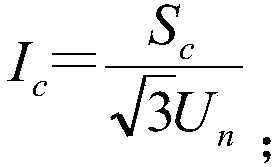
The invention discloses a design method of a tunnel mechanized construction power distribution scheme based on a drilling and blasting method. The design method comprises the following steps: firstlydetermining rated voltage Un and a power supply line design layout scheme of power utilization equipment through site inspection; computing the total Pe of the rated power Pn of all power utilizationequipment at the electricity consumption peak in various power supply lines, and then computing the active power Pc and reactive power Qc, apparent power Sc and current value Ic of each power supply line, and finally computing the total active power sum SigmaPc and the total current sum SigmaIc of various power supply lines, and determining the final assembly capacity of the transformer by the SigmaPc and the SigmaIC indexes dual-control way, thereby avoiding facility reactive loss and resource waste in the tunnel mechanized construction power distribution, and guiding the construction power distribution to adopt the power distribution scheme with the optimal energy consumption.

Description

technical field [0001] The invention relates to the technical field of tunnel construction, in particular to a design method of a tunnel mechanized construction power distribution scheme based on the drill and blast method. Background technique [0002] In the traditional artificial drilling and blasting trackless slag removal construction of tunnels, large-scale air compressors, ventilators, concrete mixers, steel processing machinery and other high-power electrical equipment are arranged outside the tunnel, and only relatively large power electrical equipment is involved in the tunnel. For lining trolleys and concrete pumps, everyone usually adopts the empirical method for construction power distribution schemes, that is, simply convert the sum of the rated power of all construction equipment motors by an empirical coefficient of 0.75 or 0.8 to determine the capacity of the power supply transformer. In this way, first, the reactive power loss of electrical equipment and tr...

Claims


Application Information

Patent Timeline
Patent Type & Authority Applications(China)
IPC IPC(8): H02J3/00
CPCH02J3/00
Inventor 李俊均肖海苑王良国
Owner GUANGDONG PROVINCIAL CHANGDA HIGHWAY ENG
Why Eureka
Try Eureka