
Camera control method and device

A control method and camera technology, which can be used in image communication, TV, color TV components, etc., can solve problems such as large power consumption, and achieve the effect of reducing power consumption.

Active Publication Date: 2020-11-27
HANGZHOU HIKVISION DIGITAL TECH
View PDF10 Cites 0 Cited by
  • Summary
  • Abstract
  • Description
  • Claims
  • Application Information

AI Technical Summary

Problems solved by technology

[0005] In order to solve the problem in the prior art that the camera collects images in real time and consumes a large amount of power, an embodiment of the present invention provides a camera control method and device

Method used


Image

  • Camera control method and device
  • Camera control method and device
  • Camera control method and device

Examples


Embodiment Construction

[0049] In order to make the object, technical solution and advantages of the present invention clearer, the implementation manner of the present invention will be further described in detail below in conjunction with the accompanying drawings.

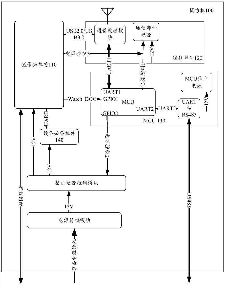
[0050] Please refer to figure 1 , which shows a schematic structural diagram of a camera provided by an exemplary embodiment of the present invention. The implementation environment may include: a camera 100 .

[0051] The camera 100 may include a camera core 110 , a communication component 120 and a micro control unit (English: MicroController Unit, MCU for short) 130 .

[0052]The camera core 110 includes at least a lens, a memory and a processor, wherein the lens is used for capturing images, the memory is used for buffering the captured images, and the processor is used for processing audio and video. The camera core 110 output interface is a standard output interface, including a Universal Serial Bus (English: Universal Serial B...


PUM


Abstract

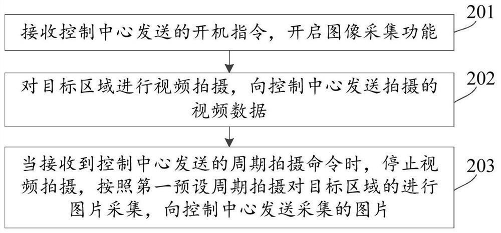
The embodiment of the invention discloses a camera control method and device, belonging to the field of video surveillance. The method includes: receiving a start-up command sent by the control center, and starting the image acquisition function; performing video shooting on the target area, and sending the captured video data to the control center; when receiving the periodic shooting command sent by the control center, Stop video shooting, collect pictures of the target area according to a first preset period, and send the collected pictures to the control center. The technical solution provided by the embodiments of the present invention solves the problem that the camera consumes a large amount of power when collecting images in real time in the prior art, and achieves the effect of reducing the power consumption of the camera and thus effectively saving power.

Description

technical field [0001] Embodiments of the present invention relate to the field of video surveillance, and in particular to a camera control method and device. Background technique [0002] A camera refers to a device with basic functions such as video recording and static image capture. The camera includes at least a camera core, which mainly includes an optical lens, an imaging chip, and a control circuit board. The picture quality, such as the number of pixels, angle of view, depth of field, etc. [0003] Usually, the process for the user to use the camera to obtain the monitoring image of the target area is: the camera uses the camera core to collect the image of the target area, and after encoding and processing the collected image data, it uses the Universal Serial Bus (English: Universal Serial Bus, referred to as: USB) is connected to the user's computer, and the image is displayed by the relevant software in the computer. [0004] When the camera monitors the targ...

Claims


Application Information

Patent Timeline
Patent Type & Authority Patents(China)
IPC IPC(8): H04N5/232
CPCH04N23/66H04N23/65
Inventor 李红卫
Owner HANGZHOU HIKVISION DIGITAL TECH
Learn More