
Printed circuit board and display device

A printed circuit board, conductive layer technology, applied in printed circuits, printed circuits, circuit devices, etc., can solve problems such as signal reflection, impedance discontinuity, etc.

Active Publication Date: 2018-10-09
HEFEI XINSHENG OPTOELECTRONICS TECH CO LTD +1
View PDF11 Cites 4 Cited by
  • Summary
  • Abstract
  • Description
  • Claims
  • Application Information

AI Technical Summary

Problems solved by technology

The impedance of the connection structure is usually much lower than the impedance of the signal line, which will cause the impedance discontinuity during the signal transmission process, which will cause problems such as signal reflection

Method used


Image

  • Printed circuit board and display device
  • Printed circuit board and display device
  • Printed circuit board and display device

Examples


Embodiment 1

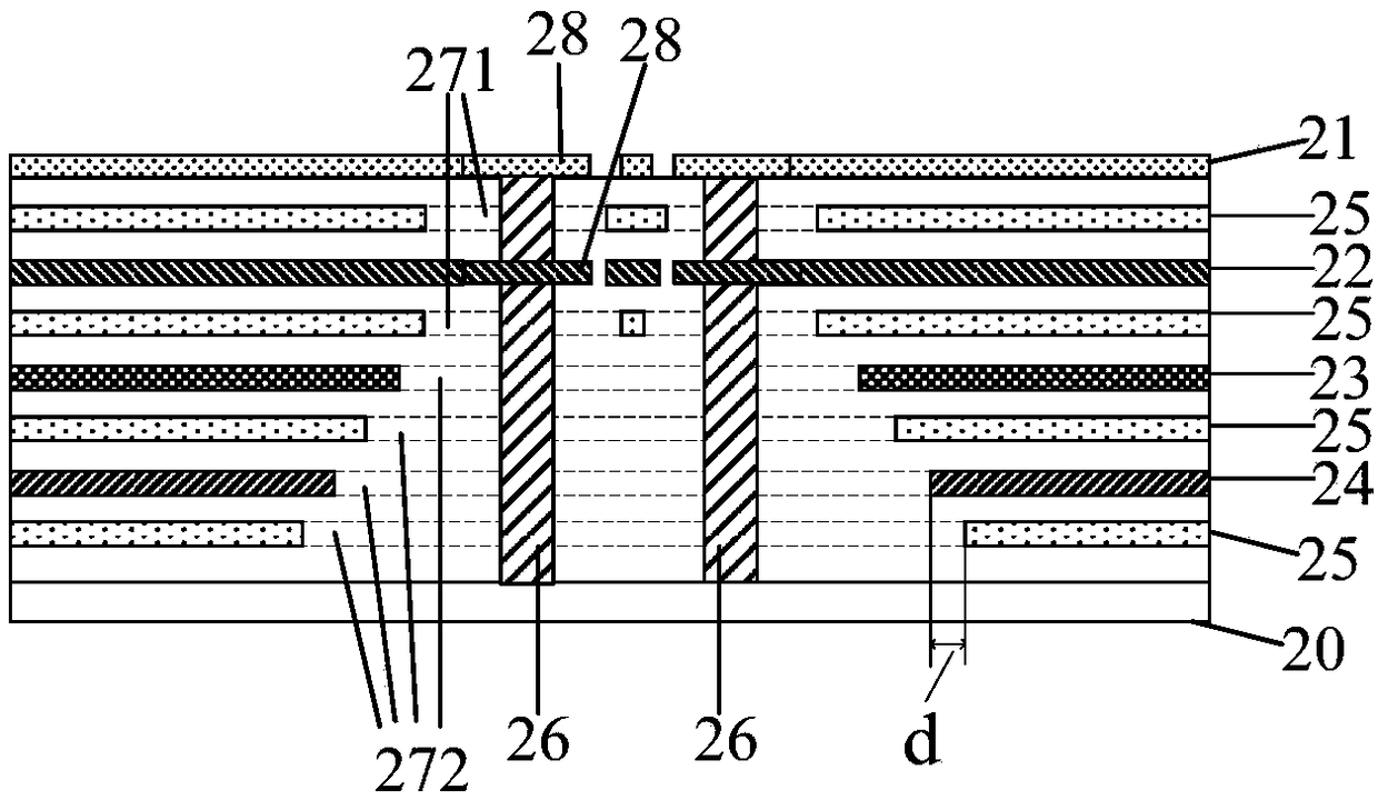
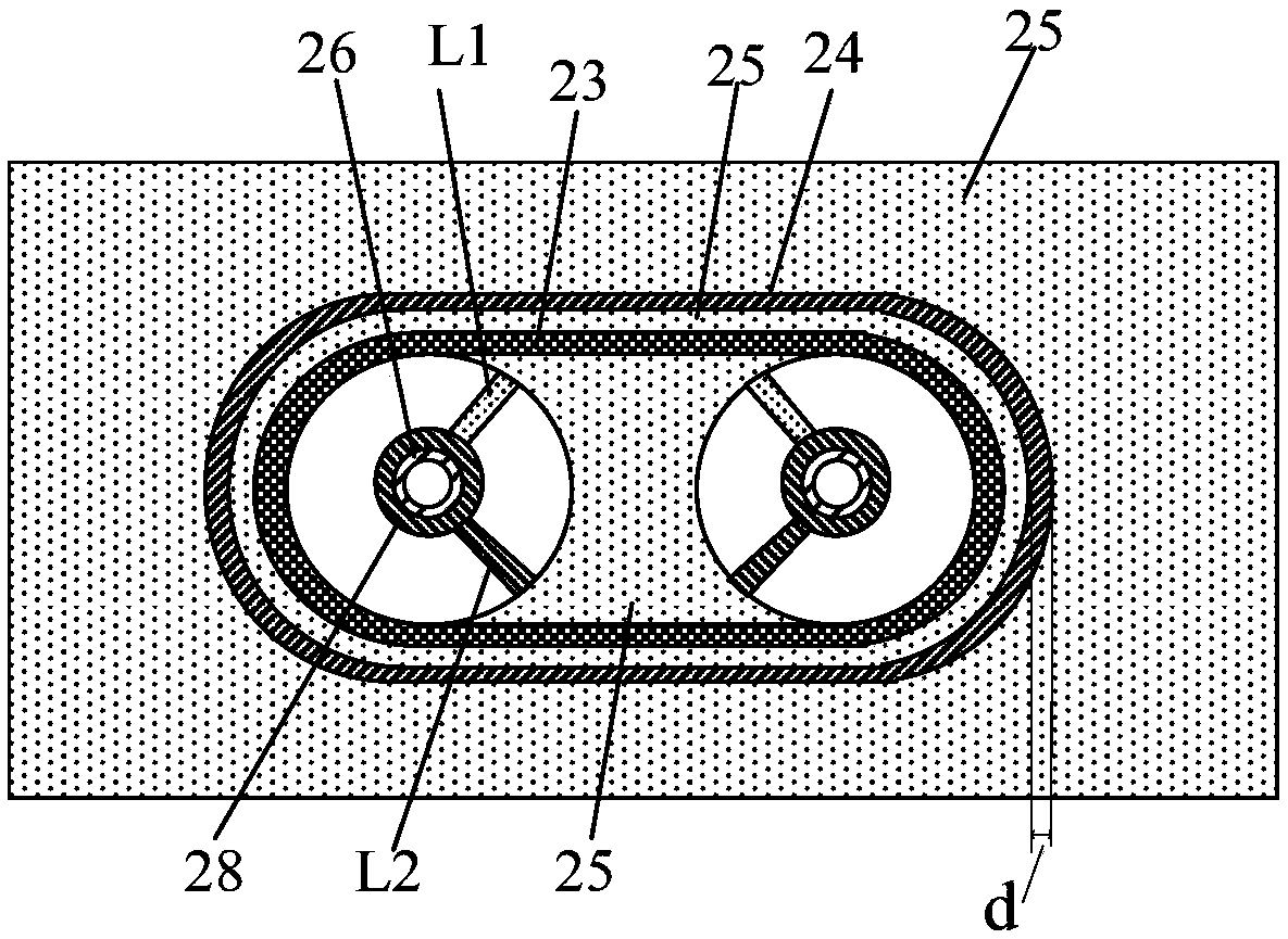
[0028] In order to achieve impedance matching between the signal line and the connection structure, Embodiment 1 of the present invention provides a printed circuit board, figure 2 It is a schematic diagram of the film layer structure of the printed circuit board provided by Embodiment 1 of the present invention, image 3 for figure 2 Bottom view of the film layer above the substrate of the printed circuit board. combine figure 2 and image 3 As shown, the printed circuit board includes insulating and spaced multi-layer conductive layers 21-25 and multiple connection structures 26, the multi-layer conductive layers 21-25 are stacked, and an insulating spacer layer is arranged between every two conductive layers. Each connection structure 26 runs through each conductive layer 21 - 25 , and the connection structure 26 connects the first signal line L1 respectively located in the conductive layer 21 and the second signal line L2 located in the conductive layer 22 . Except ...

Embodiment 2

[0041] Embodiment 2 of the present invention provides a display device, including an array substrate and a printed circuit board connected to the array substrate, and the printed circuit board is the printed circuit board provided in Embodiment 1. Optionally, a driving chip is arranged on the printed circuit board, and the printed circuit board is used to provide a driving signal of the driving chip to the array substrate.

[0042] The display device can be any product or component with a display function such as electronic paper, OLED panel, mobile phone, tablet computer, TV, monitor, notebook computer, digital photo frame, navigator, etc.

[0043] Since the printed circuit board provided by the present invention can realize impedance matching, improve the consistency of impedance during signal transmission, and reduce the signal reflection problem caused by impedance mismatch, therefore, the signal transmitted by the printed circuit board to the array substrate is more accura...


PUM


Abstract

The invention provides a printed circuit board which comprises a multilayer of conducting layers and a plurality of connecting structures which are spaced insulatively; each of the connecting structures penetrates through the conducting layers; the connecting structures are respectively connected with a first signal line and a second signal line located in two layers of the conducting layers; except for the conducting layers where the first signal line and the second signal line are located, the remaining conducting layers are provided with anti-bonding pads surrounding the connection structures; for the same connection structure, multiple anti-bonding pads, surrounding the connection structure, comprise adjacent anti-bonding pads and non-adjacent anti-bonding pads; the adjacent anti-bonding pads are the anti-bonding pads adjacent to the layer where any one of the first signal line and the second signal line is located; the non-adjacent anti-bonding pads are the anti-bonding pads having other conducting layers between the layer where any one of the first signal line and the second signal line is located; and the size of the adjacent anti-bonding pads is smaller than the size of thenon-adjacent anti-bonding pads in any direction parallel to the conducting layers. The invention further provides a display device. The printed circuit board and the display device are capable of improving the impedance continuity in a driving circuit board.

Description

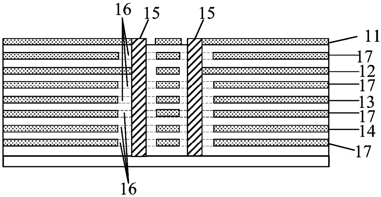
technical field [0001] The invention relates to the field of electronic products, in particular to a printed circuit board and a display device. Background technique [0002] The printed circuit board (Printed Circuit Board, PCB board) is the physical support of electronic products and an important part of signal transmission. The transmission of signals on the printed circuit board (especially the transmission of differential signals) requires high continuity of signal line impedance. . On the printed circuit board, when the signal lines of different layers are connected, they are connected through the connection structure. When there are other conductive layers between the layers where the two signal lines connected by the connection structure are located, the part of these conductive layers surrounding the connection structure is hollowed out, and the hollowed out area is called the anti-pad of the connection structure. The impedance of the connection structure is usual...

Claims


Application Information

Patent Timeline
IPC IPC(8): H05K1/02
CPCH05K1/0251H05K2201/0784G09G3/20H05K1/115H05K3/429H05K2201/09454H05K2201/09463H05K2201/09636H05K2201/09709G09G3/32H05K1/0242H05K1/0298
Inventor 谢恩明韦晓龙曹春鲍文超
Owner HEFEI XINSHENG OPTOELECTRONICS TECH CO LTD
Learn More