Pesticide spraying device with weed cutting-off function

A pesticide spraying and functional technology, which is applied in mixers with rotating stirring devices, devices for catching or killing insects, agriculture, etc., can solve the problems of uneven mixing of pesticides, limited capacity of spraying tanks, poor weeding effect, etc. Achieve the effects of improving mixing effect and mixing efficiency, increasing mixing range, and convenient control

Inactive Publication Date: 2018-10-12
FUJIAN FUXIN AGRI TECH DEV CO LTD
5 Cites 6 Cited by

AI-Extracted Technical Summary

Problems solved by technology

[0003] Ordinary pesticide spraying devices only have the function of spraying pesticides. For weeds with tenacious vitality, pesticide spraying alone may not remove them completely, and the surviving weeds will spread, resulting in poor weeding effect; Mix in proportion to make pesticides that can remove different weeds or different pests. The proportion and amount of pesticide...

Method used

Described base 1 top left side is fixedly provided with pesticide box 4, and described pesticide box 4 is fixedly provided with some pesticide bottles 5, and pesticide bottle 5 top is provided with pesticide adding port 6, and pesticide adding port 6 is connected with capping The pesticide bottle 5 is made of transparent plastic, which is convenient for observing the remaining amount of pesticides; the upper left side of the mixing box 16 is fixed with a pressure cylinder 10 through a bracket, and the left side of the bottom of the pressure cylinder 10 is connected with a medicine feed main pipe 8, and the medicine feed main pipe 8 is connected with a Several medicine feeding branch pipes 7 are set as thin as possible to the medicine feeding main pipe 8 and the medicine feeding branch pipe 7. The medicine feeding branch pipe 7 passes through the top wall of the pesticide bottle 5 and is connected to the inner bottom of the pesticide bottle 5. The top of the medicine feeding branch pipe 7 is All are provided with valves; the right side of the bottom of the pressure cylinder 10 is connected with a medicine outlet pipe 15, and the medicine outlet pipe 15 passes through the side wall of the mixing box 16 to communicate with the mixing box 16; A one-way valve 9 is provided so that the pesticide can only be injected into the pressure cylinder 10 from the medicine inlet main pipe 8 and then discharged from the medicine outlet pipe 15 without backflow; the pressure cylinder 10 is provided with a piston 11, and the top of the piston 11 is fixedly connected with a piston Rod 12, the piston rod 12 passes through the top wall of the pressure cylinder 10 and is slidably connected with the top wall of the pressure cylinder 10. The top of the pressure cylinder 10 is provided with a through hole, which is convenient for air to enter and exit the space of the pressure cylinder 10 above the piston 11, so that the air pressure is balanced and avoids Affecting the movement of the piston 11 up and down, the top of the piston rod 12 is fixedly connected with a pressure plate 14, a return spring 13 is arranged between the pressure plate 14 and the pressure cylinder 10, the return spring 13 is sleeved on the piston rod 12, and the return spring 13 is a compression spring, Give the pressure plate 14 an upward force, so that the piston 11 is at the top of the pressure cylinder 10; when it is necessary to extract pesticides, open the valve on one of the feed branch pipes 7, press the pressure plate 14 downward, and first discharge the air in the pressure cylinder 10 , loosen the pressure plate 14, under the action of negative pressure, the required pesticide enters the pressure cylinder 10, press it again to press the pesticide into the mixing box 16, if it is necessary to replace the pesticide, close the original valve and open another one to feed the pesticide The valve on the branch pipe 7 allows another kind of pesticide to enter the pressure cylinder 10, press the pressing plate 14 repeatedly, and then another kind of pesticide can be added into the mixing box 16; since the volume of the pressure cylinder 10 remains unchanged, each time the pressing plate 14 is pressed to mix The amount of pesticides added in the box 16 remains unchanged. According t...

Abstract

The invention discloses a pesticide spraying device with a weed cutting-off function. The pesticide spraying device comprises a base. A mixing box is fixedly arranged on the top of the base, a motor is fixedly arranged in the center of the top of the mixing box, a motor shaft at the bottom end of the motor penetrates through the bottom wall of the mixing box to be fixedly connected with a rotary shaft, and multiple stirring blades are fixedly installed on the left side and the right side of the rotary shaft. An energy supply box is fixedly arranged on the right side of the top of the base, a water pump is fixedly arranged on the top of the energy supply box, and the water inflow end of the water pump is connected with a water drawing pipe. The water outflow end of the water pump is connected with a water outflow pipe, and the right end of the water outflow pipe is connected with a sprayer. A second motor is fixedly arranged on the right side of the top of the base, a motor shaft at thebottom end of the second motor penetrates through the base to be fixedly connected with a second rotary shaft, and a cutter is fixedly installed at the bottom end of the second rotary shaft. The cutter rotates to cut off weeds on the ground, the weeding effect is further improved, the weeds which are cut off can be moved away, and later farming is promoted.

Application Domain

Technology Topic

Image

  • Pesticide spraying device with weed cutting-off function
  • Pesticide spraying device with weed cutting-off function
  • Pesticide spraying device with weed cutting-off function

Examples

  • Experimental program(1)

Example Embodiment

[0020] The technical solutions in the embodiments of the present invention will be clearly and completely described below in conjunction with the accompanying drawings in the embodiments of the present invention. Obviously, the described embodiments are only a part of the embodiments of the present invention, rather than all the embodiments. Based on the embodiments of the present invention, all other embodiments obtained by those of ordinary skill in the art without creative work shall fall within the protection scope of the present invention.
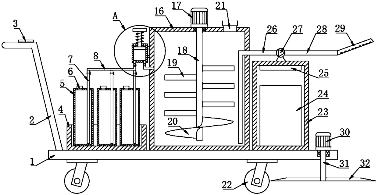
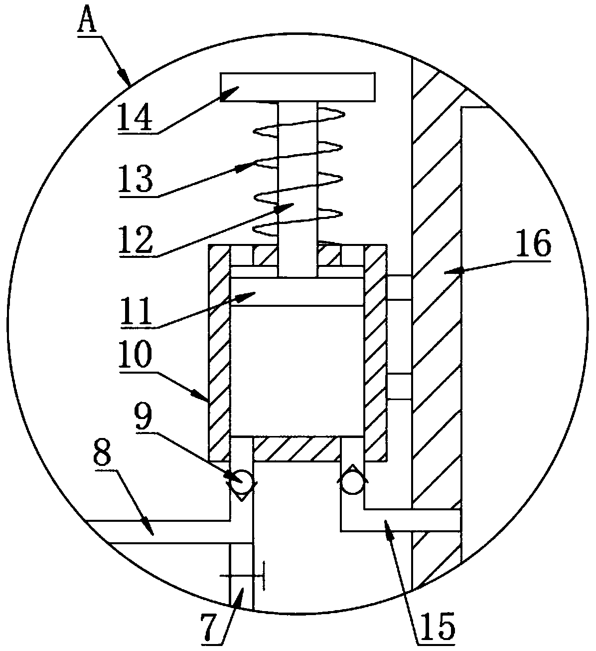
[0021] See Figure 1~3 In the embodiment of the present invention, a pesticide spraying device with weed removal function includes a base 1, a universal wheel 22 is installed at the bottom of the base 1, and two front and rear push rods are fixedly provided on the left side of the top of the base 1 2; The top of the base 1 is fixedly provided with a mixing box 16, the right side of the top of the mixing box 16 is provided with a feeding port 21, the feeding port 21 is connected with a cover, the top center of the mixing box 16 is fixedly provided with a first motor 17 , The first motor shaft at the bottom of the first motor 17 passes through the bottom wall of the mixing box 16 and is fixedly connected with a first rotating shaft 18, the first rotating shaft 18 is located in the mixing box 16, and the left and right sides of the first rotating shaft 18 are fixedly installed with a number of mixing The blades 19 and the left and right mixing blades 19 are arranged staggered to increase the mixing range. The bottom end of the first rotating shaft 18 is also fixedly installed with a spiral blade 20. Pesticide and water are added to the mixing box 16, and the mixing blade 19 and the spiral blade 20 rotate During stirring and mixing, when the spiral blade 20 rotates, the liquid at the bottom of the mixing box 16 is driven to move upward, thereby causing the pesticide to roll up and down, improving the mixing effect and mixing efficiency;
[0022] A pesticide box 4 is fixedly arranged on the left side of the top of the base 1, a number of pesticide bottles 5 are fixedly arranged in the pesticide box 4, a pesticide addition port 6 is provided on the top of the pesticide bottle 5, and the pesticide addition port 6 is connected with a cap. 5 The material is made of transparent plastic, which is convenient for observing the remaining amount of pesticide; the upper left side of the mixing box 16 is fixedly provided with a pressure cylinder 10 through a bracket, and the bottom left side of the pressure cylinder 10 is connected with a medicine feeding main pipe 8, which is connected with several medicine feeding pipes. The branch pipe 7, the main medicine feeding pipe 8 and the medicine feeding branch pipe 7 are arranged as thin as possible, the medicine feeding branch pipe 7 passes through the top wall of the pesticide bottle 5 and is connected to the inner bottom of the pesticide bottle 5, and the top of the medicine feeding branch pipe 7 is provided with Valve; the right side of the bottom of the pressure cylinder 10 is connected with a medicine outlet pipe 15, the medicine outlet pipe 15 passes through the side wall of the mixing box 16 and communicates with the mixing box 16; the medicine inlet manifold 8 and the medicine outlet pipe 15 are provided with a single top To the valve 9, the pesticide can only be injected into the pressure cylinder 10 from the medicine inlet pipe 8 and then discharged from the medicine outlet pipe 15 without returning; the pressure cylinder 10 is provided with a piston 11, and the top of the piston 11 is fixedly connected with a piston rod 12, The piston rod 12 passes through the top wall of the pressure cylinder 10 and is slidably connected to the top wall of the pressure cylinder 10. A through hole is provided on the top of the pressure cylinder 10 to facilitate air in and out of the space of the pressure cylinder 10 above the piston 11, so as to balance the air pressure and avoid affecting the piston 11. Move up and down, the top of the piston rod 12 is fixedly connected with a pressure plate 14, a return spring 13 is arranged between the pressure plate 14 and the pressure cylinder 10, the return spring 13 is sleeved on the piston rod 12, the return spring 13 is a compression spring, and the pressure plate 14 The upward force makes the piston 11 at the top of the pressure cylinder 10; when pesticides need to be extracted, open the valve on one of the medicine feeding branch pipes 7 and press the pressure plate 14 downward to discharge the air in the pressure cylinder 10 and release it The pressure plate 14, under the action of negative pressure, the required pesticide enters the pressure cylinder 10. Press again to press the pesticide into the mixing box 16. If the pesticide needs to be replaced, close the original valve and open another branch pipe 7 The valve allows another pesticide to enter the pressure cylinder 10. Repeat pressing the pressure plate 14 to add another pesticide to the mixing box 16; since the volume of the pressure cylinder 10 remains unchanged, each time the pressure plate 14 is pressed into the mixing box 16 The amount of pesticide added remains unchanged. According to the ratio of different pesticides and the volume of the mixing box 16, the amount of each pesticide needed to be added can be easily calculated, and the pressing plate 14 corresponding to the corresponding number of times can be pressed. It is required that the error is not large and will not affect the efficacy of the drug. It is more efficient and more accurate than manual measurement or adding pesticides based on experience. It is easy to add and mix multiple pesticides in proportion;
[0023] An energy supply box 23 is fixedly arranged on the right side of the top of the base 1, and a water pump 27 is fixedly arranged on the top of the energy supply box 23. The water inlet end of the water pump 27 is connected with a water pumping pipe 26, which is connected through the side wall of the mixing box 16 To the inner bottom of the mixing tank 16; the water outlet end of the water pump 27 is connected with a water outlet pipe 28, and the right end of the water outlet pipe 28 is connected with a spray head 29; the water pump 27 is activated, and the pesticide in the mixing tank 16 can be sprayed from the spray head 29;
[0024] A second motor 30 is fixedly arranged on the top right side of the base 1, the first motor shaft at the bottom of the second motor 30 passes through the base 1 and is fixedly connected with a second rotating shaft 31, and a cutter 32 is fixedly installed at the bottom of the second rotating shaft 31, The weeds on the ground can be removed by rotating the cutter 32 to further improve the weeding effect. The removed weeds can be removed, which is convenient for later cultivation, etc.;
[0025] A storage battery 24 is fixed at the bottom of the power supply box 23, and a control circuit board 25 is fixed at the top of the power supply box 23. The control circuit board 25 is connected to the storage battery 24, the first motor 17, the water pump 27, and the second through wires. The two motors 30 are connected. A control switch 3 is provided at the handle of the push rod 2. The control switch 3 is connected to the control circuit board 25 through wires; the control switch 3 includes the control switch of the first motor 17 and the control switch of the water pump 27 The control switches of the second motor 30 and the control switches are respectively arranged at the handles of the front and rear push rods 2, making the operation more convenient.
[0026] For those skilled in the art, it is obvious that the present invention is not limited to the details of the foregoing exemplary embodiments, and the present invention can be implemented in other specific forms without departing from the spirit or basic characteristics of the present invention. Therefore, from any point of view, the embodiments should be regarded as exemplary and non-limiting. The scope of the present invention is defined by the appended claims rather than the foregoing description, and therefore it is intended to fall within the claims. All changes within the meaning and scope of equivalent elements of are included in the present invention. Any reference signs in the claims should not be regarded as limiting the claims involved.
[0027] In addition, it should be understood that although this specification is described in accordance with the embodiments, not every embodiment only includes an independent technical solution. This narration in the specification is only for clarity, and those skilled in the art should consider the specification as a whole The technical solutions in the embodiments can also be appropriately combined to form other implementations that can be understood by those skilled in the art.

PUM

no PUM

Description & Claims & Application Information

We can also present the details of the Description, Claims and Application information to help users get a comprehensive understanding of the technical details of the patent, such as background art, summary of invention, brief description of drawings, description of embodiments, and other original content. On the other hand, users can also determine the specific scope of protection of the technology through the list of claims; as well as understand the changes in the life cycle of the technology with the presentation of the patent timeline. Login to view more.

Similar technology patents

Pallet dolly

InactiveUS20080012260A1Easy to moveSafer and quicker and efficientUnderstructuresHand carts with one axisEngineeringPallet
Owner:CORMARK

Lamp and vehicle frame thereof

InactiveCN102853275AEasy to moveLamps are easy to moveLighting support devicesElectric lighting with built-in generatorsVehicle frameFastener
Owner:OCEANS KING LIGHTING SCI&TECH CO LTD +1

Classification and recommendation of technical efficacy words

  • Easy to control
  • Easy to move

Container base structure responsive to vacuum related forces

ActiveUS20090159556A1Restrain all pressure and forceEasy to moveLarge containersRigid containersVacuum pressure
Owner:AMCOR RIGID PLASICS USA LLC
Why Eureka
Try Eureka