Check patentability & draft patents in minutes with Patsnap Eureka AI!

Robot slipping detecting method and robot slipping correcting method

A detection method and robot technology, applied in the direction of instruments, manipulators, measuring devices, etc., can solve the problems of no movement of the robot, map errors, poor navigation accuracy, etc., to prevent slippage and false detection, ensure accuracy, and improve accuracy. Effect

Active Publication Date: 2018-10-12
AMICRO SEMICON CORP
View PDF5 Cites 36 Cited by
  • Summary
  • Abstract
  • Description
  • Claims
  • Application Information

AI Technical Summary

Problems solved by technology

2. When the collision sensor of the robot is abnormal, the robot cannot detect the collision, and the robot will keep idling against the obstacle, causing the code disc to calculate that the robot has moved a relatively large distance, but in fact the robot has not moved
At this time, the robot still records the error data generated when it is offset or slipping as normal data, which makes the constructed map wrong, causing the robot to mistakenly think that this area is a new area, and cannot end the cleaning of this area and navigate to other areas. As a result, the cleaning efficiency of the robot is very low, and the navigation accuracy is also poor.
[0003] Since the road conditions on which the robot travels are very complex, and different road conditions will have different effects on the detection results of the robot, it can be determined whether the robot is slipping only by relying on one data detection and judgment, or by using the code disc detection alone. There is a case of misjudgment

Method used


Image

  • Robot slipping detecting method and robot slipping correcting method
  • Robot slipping detecting method and robot slipping correcting method

Examples


Embodiment Construction

[0039] The technical solutions in the embodiments of the present invention will be described in detail below with reference to the drawings in the embodiments of the present invention. It should be understood that the specific embodiments described below are only used to explain the present invention, not to limit the present invention.

[0040] It should be noted that in this article, relational terms such as first and second are only used to distinguish one entity or operation from another entity or operation, and do not necessarily require or imply that there is a relationship between these entities or operations. There is no such actual relationship or order between them.

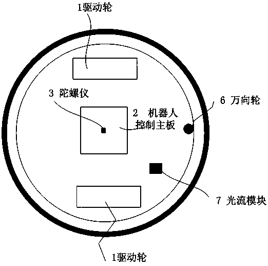
[0041] The robot carrier of the present invention is equipped with gyroscope and is used for the detection of rotation angle, and odometer is used for the detection of travel distance, and the sensor that can detect wall surface distance is housed, and the sensor that detects wall surface distance can b...


PUM


Abstract

The invention provides a robot slipping detecting method and a robot slipping correcting method. According to coded disc data of a robot within preset time, a first displacement increment and a firstangular velocity are obtained; according to light stream data of the robot within the same preset time, a second displacement increment is obtained; according to gyroscope data of the robot within thesame preset time, a second angular velocity is obtained; whether a difference value of the first angular velocity and the second angular velocity is larger than a first preset pose threshold value ornot is judged, it is judged that the robot slips if the difference value is larger than the first preset pose threshold value, and the light stream data are used for updating map coordinates; or whether a difference value of the first displacement increment and the second displacement increment is larger than a second preset pose threshold value or not is further judged, it is judged that the robot slips if the difference value is larger than the second preset pose threshold value, or it is judged that the robot does not slip, and the coded disc data are used for updating the map coordinates.The problem that the robot slopping detection accuracy is not high is solved, and the robot map accuracy is improved

Description

technical field [0001] The invention relates to the field of robot detection and control, in particular to a detection method and a correction method for robot slipping. Background technique [0002] When the robot based on inertial navigation navigates back to the charging stand, it is based on the global grid map. This method assumes that the global map is relatively accurate, but in practical applications, there are often various abnormal situations that lead to The robot will not move according to the predetermined mathematical model, which will lead to errors in the position calculation results of the robot, which will cause the so-called slipping of the robot. These abnormal situations include: 1. When the robot is moving on the carpet, due to the force vector applied by the carpet to the robot, the movement of the robot is not only affected by friction but also by the force exerted by the carpet on the robot. The resulting movement is affected by the resultant force ...

Claims


Application Information

Patent Timeline
IPC IPC(8): B25J9/16B25J13/08G01C21/16
CPCB25J9/1653B25J9/1694B25J13/088G01C21/165
Inventor 戴剑锋
Owner AMICRO SEMICON CORP
Features
  • R&D
  • Intellectual Property
  • Life Sciences
  • Materials
  • Tech Scout
  • Unparalleled Data Quality
  • Higher Quality Content
  • 60% Fewer Hallucinations
Learn More