HVAC device used for vehicle and air conditioner mode conversion method

A technology for mode conversion and vehicle use, which is applied to vehicle parts, transportation and packaging, and air handling equipment. It can solve the problems of large HVAC size, low fan speed and low fan speed, and achieve low fan speed and high fan efficiency. , the effect of reducing the temperature difference between left and right

Inactive Publication Date: 2018-10-12
ZHIDOU ELECTRIC VEHICLE CO LTD
View PDF8 Cites 2 Cited by
  • Summary
  • Abstract
  • Description
  • Claims
  • Application Information

AI Technical Summary

Problems solved by technology

The size of the traditional HVAC is large, the system structure is complex, and the system enters the air through one side of the fan installed in the air intake duct, which has the disadvantages of high wind pressure under the same air volume requirements, large wind noise during operation, and high fan speed and low efficiency. Therefore, it is an urgent problem to be solved to design a vehicle HVAC device with a compact structure, a simple system, low wind pressure under the same air volume requirements, low wind noise during system operation, low fan speed and high efficiency, and an air-conditioning mode conversion method.

Method used


Image

  • HVAC device used for vehicle and air conditioner mode conversion method
  • HVAC device used for vehicle and air conditioner mode conversion method
  • HVAC device used for vehicle and air conditioner mode conversion method

Examples


Embodiment Construction

[0018] The present invention will be further described below in conjunction with the accompanying drawings.

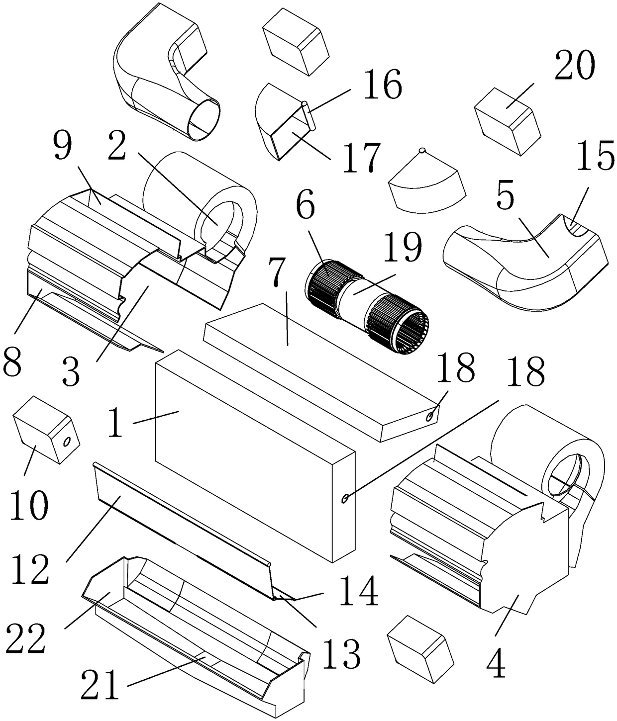
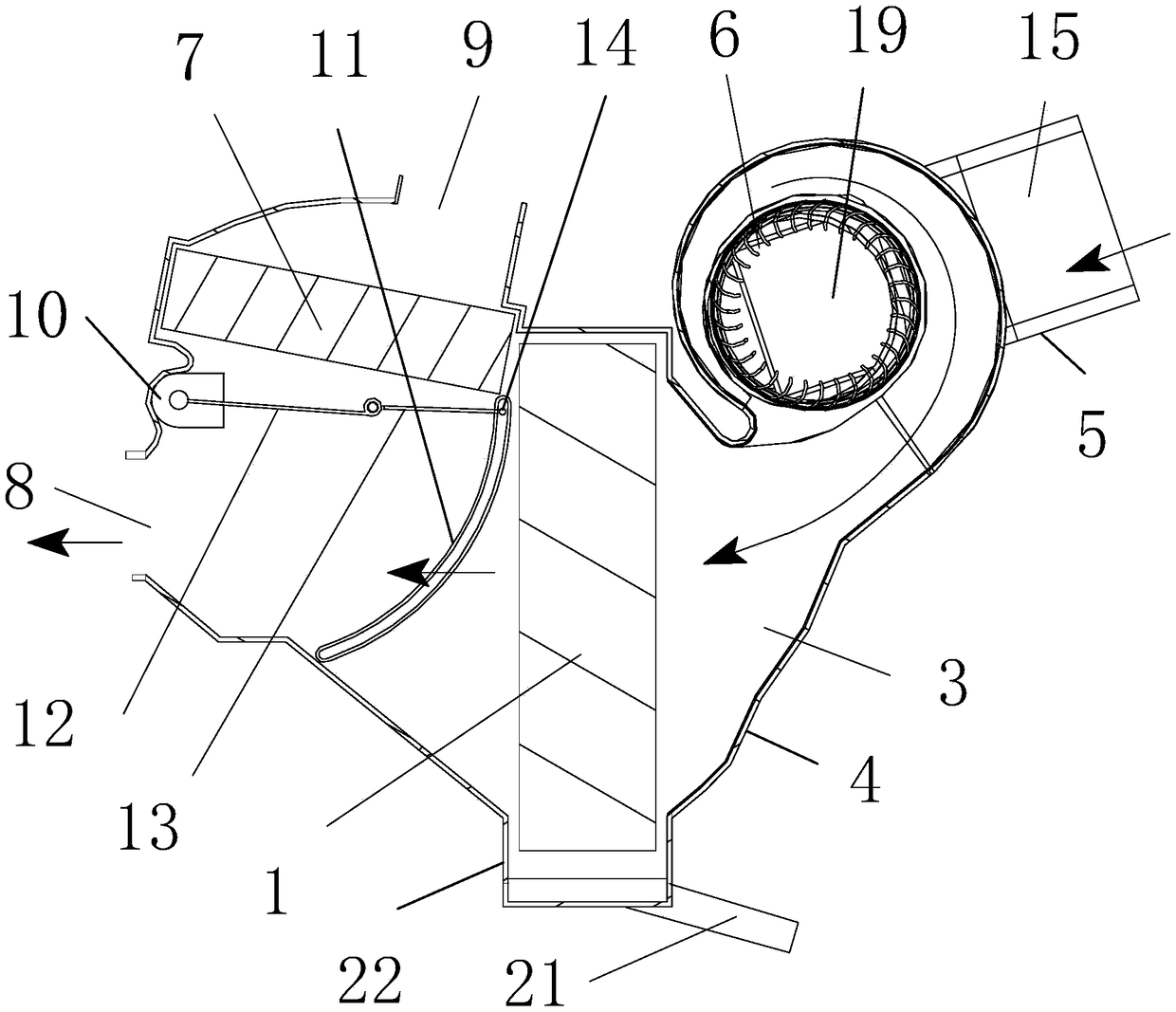
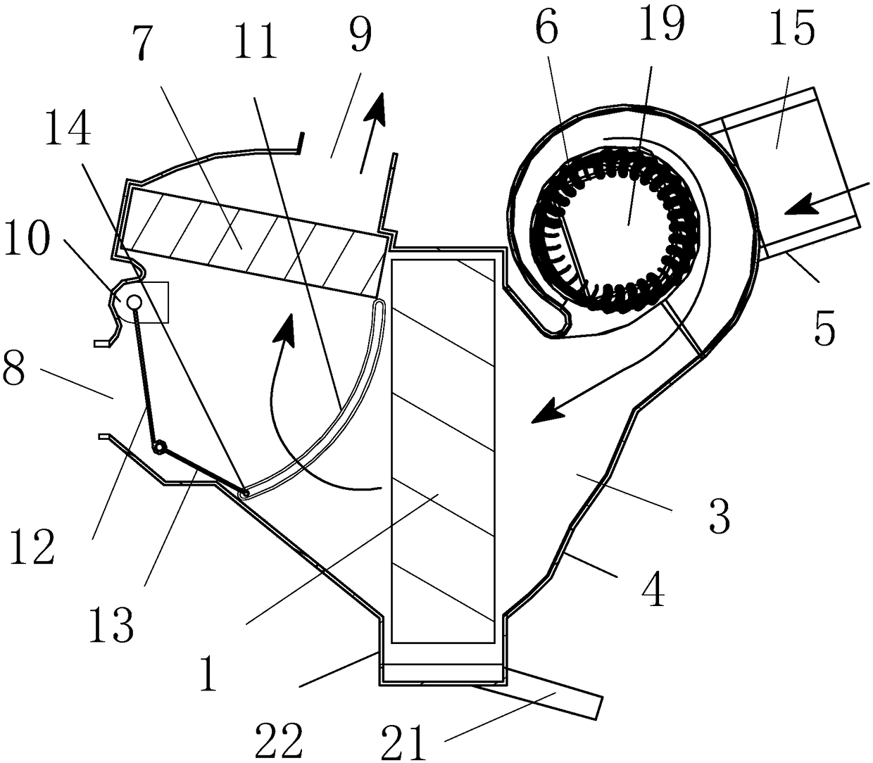
[0019] as attached figure 1 , attached figure 2 , attached image 3 Shown: an HVAC device for a vehicle, comprising: an evaporator 1, two half shells 4 provided with laterally symmetrical air inlet holes 2 and a half air outlet chamber 3 communicating with the air inlet holes 2, two half shells The opposite ends of the air outlet chamber 3 are connected to form the air outlet chamber, and the air conditioning mode conversion device is installed in the air outlet chamber, and two air inlet boxes are equipped with an internal and external circulation air mode conversion device and are connected with the outer ends of the air inlet holes 2 by corresponding screws. 5. There are two linkage drive devices corresponding to the blower impeller 6 located in the air inlet 2, and the air conditioner heater 7 located on the upper part of the air outlet cavity; the evaporator 1 ...


PUM


Abstract

The invention aims at providing an HVAC device used for a vehicle and an air conditioner mode conversion method. The HVAC device used for the vehicle comprises an evaporator, two half shells, an air conditioner mode conversion device, two air inflow boxes, a linkage drive device and an air conditioner heater, wherein the two half shells are provided with air inflow holes and half air outflow cavities communicating with the air inflow holes, and an air outflow cavity is formed by the two half air outflow cavities; the air conditioner mode conversion device is arranged in the air outflow cavity;the two air inflow boxes are provided with internal and external circulating air mode conversion devices and correspondingly connected with the outer ends of the air inflow holes one to one; the linkage drive device is provided with two air blowing impellers correspondingly located in the air flow holes one to one; and the air conditioner heater is arranged on the upper portion of the air outflowcavity; the evaporator is located in the air outflow cavity and opposite to outlets of the air inflow holes; and the front ends of the half shells are provided with face blowing air outlets communicating with the air outflow cavity and opposite to the evaporator, and the upper ends of the half shells are provided with defrosting air outlets communicating with the air outflow cavity and opposite to the upper end of the air conditioner heater. By the adoption of the HVAC device used for the vehicle, under the requirement of the same air volume, the rotation speed of a draught fan is lower, theefficiency of the draught fan is higher, and energy conservation and noise reduction are facilitated.

Description

technical field [0001] The invention relates to the field of air conditioning, in particular to a vehicle HVAC device. Background technique [0002] HVAC (English: Heating, Ventilation, Air-conditioning and Cooling) is the air conditioning system, which is a control system including temperature, humidity, air cleanliness and air circulation; Under the action of the compressor, evaporation or condensation occurs, which causes the evaporation or condensation of the surrounding air to achieve the purpose of changing the temperature and humidity. The invention of Chinese patent application No. CN201410853666.1 discloses an HVAC system for automobile air conditioners, including an air inlet assembly and an evaporator assembly connected to the air inlet assembly; the air inlet assembly includes an air inlet, an air inlet filter A blower is provided inside the housing, and an air outlet connected to the evaporator assembly is arranged on the housing; the evaporator assembly includ...

Claims


Application Information

Patent Timeline
Patent Type & Authority Applications(China)
IPC IPC(8): B60H1/34B60H1/00
CPCB60H1/00007B60H1/00642B60H1/34B60H2001/3471
Inventor 张军鲍文光闫优胜樊晓浒何志刚
Owner ZHIDOU ELECTRIC VEHICLE CO LTD
Why Eureka
Try Eureka