A waste gas treatment equipment for environmental engineering

A waste gas treatment equipment and environmental engineering technology, which is applied in the field of environmental engineering, can solve the problems of equipment safety hazards, cumbersome operation, heat escape, etc., achieve the effect of short replacement time, scientific and reasonable structure, and avoid exhaust gas overflow

Active Publication Date: 2020-11-24
东营金辉环保科技有限公司
View PDF7 Cites 0 Cited by
  • Summary
  • Abstract
  • Description
  • Claims
  • Application Information

AI Technical Summary

Problems solved by technology

[0003] The present invention provides a kind of exhaust gas treatment equipment for environmental engineering, which can effectively solve the problem that the catalyst of the exhaust gas treatment equipment in the existing catalytic oxidation process proposed in the above background technology is first decomposed by reaction, and then synthesized by reaction. Although the total mass has not changed, the post-reaction The produced particles fall off the catalytic bed, which causes the catalyst to gradually decrease during the reaction process. The existing exhaust gas treatment equipment cannot quickly replace the catalytic bed, and it needs to be replaced after the equipment is cooled, resulting in waste of heat energy and time for reheating. Reduce the processing efficiency of the exhaust gas treatment equipment, and at the same time, the scattered catalyst particles fall on the bottom of the reaction box or block the ventilation pipe, which is not convenient for workers to clean up, and at the same time causes damage to the equipment. Under the action of the high temperature inside the reaction box, the top edge Cracks are prone to appear in the welding place, resulting in the leakage of exhaust gas and the escape of heat, resulting in environmental pollution and energy waste. The existing device for detecting cracks is cumbersome and requires high operation requirements, which is not conducive to popularization to workers, resulting in failure to repair equipment in time , which reduces the efficiency of the equipment in treating exhaust gas, and at the same time causes the problem of potential safety hazards of the equipment

Method used


Image

  • A waste gas treatment equipment for environmental engineering
  • A waste gas treatment equipment for environmental engineering
  • A waste gas treatment equipment for environmental engineering

Examples


Embodiment

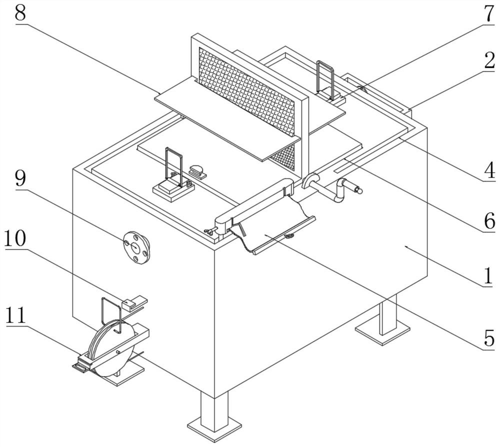
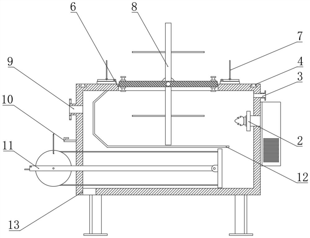
[0027] Example: such as Figure 1-5 As shown, the present invention provides a technical solution, a kind of waste gas treatment equipment for environmental engineering, comprising a reaction box 1, a burner 2 is installed on one side of the reaction box 1, and the surface of one side of the reaction box 1 and the top of the burner 2 An air inlet 3 is provided at the corresponding position, and a chute 4 is provided on the outer ring of the upper surface of the reaction box 1 .

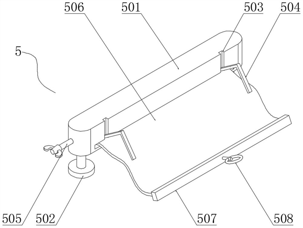
[0028] A detection mechanism 5 is installed above the chute 4. The detection mechanism 5 includes a storage box 501, a sliding column 502, a storage groove 503, a sealing rod 504, a storage shaft 505, a plastic film 506, a limit plate 507 and a pull ring 508, and the storage box 501 Sliding columns 502 are installed at the bottom. In order to ensure that the storage box 501 can maintain stable movement and steering in the chute 4 through the sliding columns 502, the number of sliding columns 502 is se...


PUM


Abstract

The invention discloses waste gas treatment equipment for environmental engineering. The waste gas treatment equipment comprises a reaction box body; a sliding groove is formed in the outer ring of the upper surface of the reaction box body; a detection mechanism is arranged above the sliding groove; the two ends of an adjusting rope are connected to a compressed gas cleaning plate; a flow baffleis arranged in the reaction box body; a sliding column is arranged at the bottom of a storage box; and partition plates are arranged on the two sides of the middle of a catalytic bed. The waste gas treatment equipment has the advantages of being scientific and reasonable in structure and safe and convenient to use, a plastic film is fixed to the edges of the reaction box body through sealing rods,so that whether cracks exist at the edge position can be effectively known, the generation of the cracks of the reaction box body can be conveniently found in time, and the hidden danger in installation, the escape of pollution waste gas and the waste of heat energy can be avoided; and a rocking handle is rotated to enable sealing plates to drive the catalytic bed to rotate, the operation is simple and easy to carry out, workers can conveniently and quickly replace the catalytic bed inside the reaction box body, so that the situation that the environment pollution is caused due to the fact that the waste gas in the reaction box body escapes can be avoided.

Description

technical field [0001] The invention relates to the technical field of environmental engineering, in particular to waste gas treatment equipment for environmental engineering. Background technique [0002] Waste gas treatment equipment mainly refers to a kind of environmental protection equipment that protects the environment and purifies the air by recycling or removing or reducing harmful components of exhaust gas by using different technologies, so that our environment will not be polluted. In the waste gas treatment process, The catalytic oxidation process has the advantages of small footprint, low investment, low operating cost, convenient management, and ready-to-use. The exhaust gas treatment equipment of the catalytic oxidation process has a wide range of applications, especially for the treatment of large-volume, medium-to-high-concentration exhaust gas. It has a very good removal rate of harmful pollutants, mainly when the malodorous gas passes through the catalyti...

Claims


Application Information

Patent Timeline
Patent Type & Authority Patents(China)
IPC IPC(8): F23G7/07F23G5/44
CPCF23G5/44F23G7/061F23G7/07Y02A50/20
Inventor 王兴生
Owner 东营金辉环保科技有限公司
Why Eureka
Try Eureka