
Ultrathin diffraction optical element based on ultra-structure surface

A diffractive optical element and metasurface technology, applied in the field of optics, can solve problems such as reduced precision, complex processing, and increased number of quantized steps, achieving the effects of simplified structure, great flexibility, and promotion of integration

Active Publication Date: 2018-10-12
INST OF OPTICS & ELECTRONICS - CHINESE ACAD OF SCI
View PDF2 Cites 10 Cited by
  • Summary
  • Abstract
  • Description
  • Claims
  • Application Information

AI Technical Summary

Problems solved by technology

[0004] The current diffraction elements are designed and constructed based on the law of refraction and diffraction, so they are sensitive to wavelength changes. In order to solve the problem of symmetrical images in the existing technology and improve the efficiency of the diffraction system, the number of quantization steps must be increased, resulting in complex processing and reduced accuracy.

Method used


Image

  • Ultrathin diffraction optical element based on ultra-structure surface
  • Ultrathin diffraction optical element based on ultra-structure surface
  • Ultrathin diffraction optical element based on ultra-structure surface

Examples


Embodiment Construction

[0021] The present invention and embodiments are further described below in conjunction with the drawings:

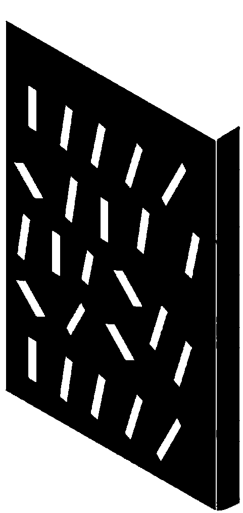
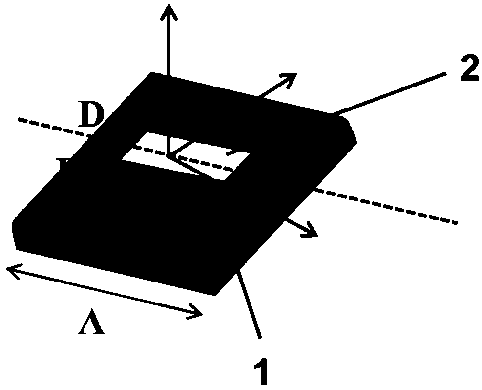
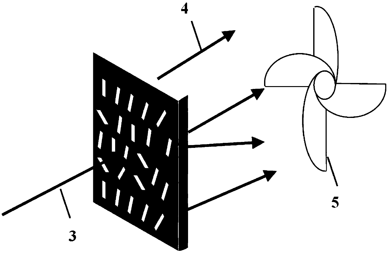
[0022] See figure 1 As shown, an ultra-thin diffractive optical element based on a meta-surface includes a diffractive optical element body. The body is a planar structure. One side of the structure is a metal nanorod structure. The orientation angle of the nanorod Different, used to adjust the phase of incident light.

[0023] The relationship between the phase modulation of the light wavefront and the direction angle of the nanorod satisfies the equation Change within 0~π. The sign of Φ is determined by the polarization of the incident light. The incident light and the outgoing light are right-handed circular polarization and left-handed circular polarization, respectively, so the phase is positive, and the incident light and outgoing light are left-handed circular polarization and right-handed circular polarization, respectively. The phase is negative.

[0024] See fig...


PUM

PropertyMeasurementUnit
Lengthaaaaaaaaaa
Heightaaaaaaaaaa
Thicknessaaaaaaaaaa

Abstract

The present invention discloses an ultrathin diffraction optical element based on an ultra-structure surface. The element comprises a diffraction optical element body which is an ultra-thin plane structure, the base of the ultra-thin plane structure is glass materials, one surface of the base is a two-dimensional nanostructure which are metal nanorods distributed in different directions, the sizesof the metal nanorods are a nanometer level, the direction angles [phi] of the metal nanorods decide the phase modulation of the metal nanorods for light, the modulation of direction angles of the metal nanorods for the light phase meets a phase equation [Phi]=+-2[phi], the phase [Phi] is changed in a range of 0-2[pi], the plus or minus of the phase [Phi] is decided by the polarization directionsof the incident light and the transmitting light, if the incident light and the transmitting light are right-hand circular polarization and left-hand circular polarization, the phase is plus, and ifthe incident light and the transmitting light are left-hand circular polarization and right-hand circular polarization, the phase [Phi] is minus. Under the same diffraction effect, the structure of the diffraction optical element is two-step, the element is thinner and simpler, symmetrical images are eliminated, and broadband imaging is achieved.

Description

Technical field [0001] The invention relates to an ultra-thin diffractive optical element based on a superstructure surface, and belongs to the field of optical technology. Background technique [0002] In 1967, the former Soviet Union physicist VG Veselago put forward a bold conjecture: If a material has both a negative dielectric constant ε and a negative permeability μ, its refractive index will be negative, and the electric and magnetic fields in the material The left-hand rule is satisfied between the wave vector and the wave vector, which is called "left-handed material" or "negative refractive index material". Until 2001, the American physicist D.R. Smith used metal wires and metal split resonant rings to construct a negative refractive index material in the microwave band for the first time, and for the first time experimentally verified the existence of left-handed materials. At this time, Veselago proposed that this peculiar material not only refers to the left-handed ...

Claims


Application Information

Patent Timeline
IPC IPC(8): G02B27/42G02B27/28
CPCG02B27/286G02B27/42
Inventor 张满付小芳唐勇邓启凌史立芳
Owner INST OF OPTICS & ELECTRONICS - CHINESE ACAD OF SCI
Learn More