

Trajectory tracking method and system for site unmanned vehicle
A trajectory tracking and unmanned vehicle technology, applied in control/regulation systems, motor vehicles, vehicle position/route/height control, etc., to reduce equipment costs, promote technology implementation, and improve robustness and adaptability
- Summary
- Abstract
- Description
- Claims
- Application Information
AI Technical Summary
Problems solved by technology
Method used
Image

Examples
Embodiment 1
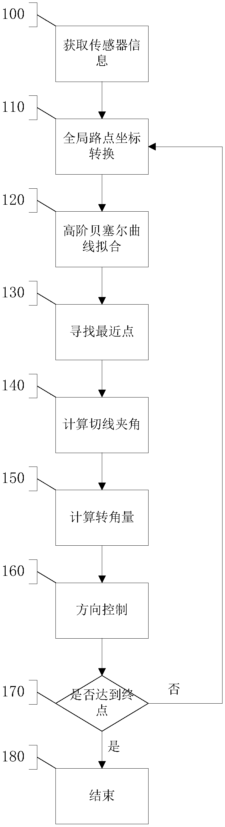
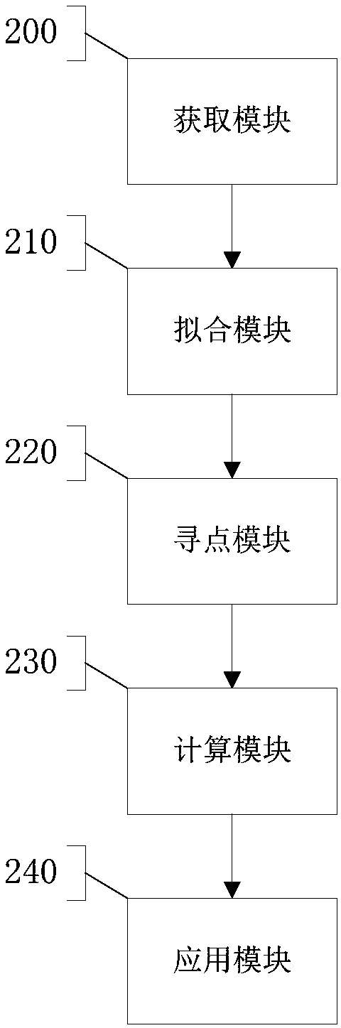
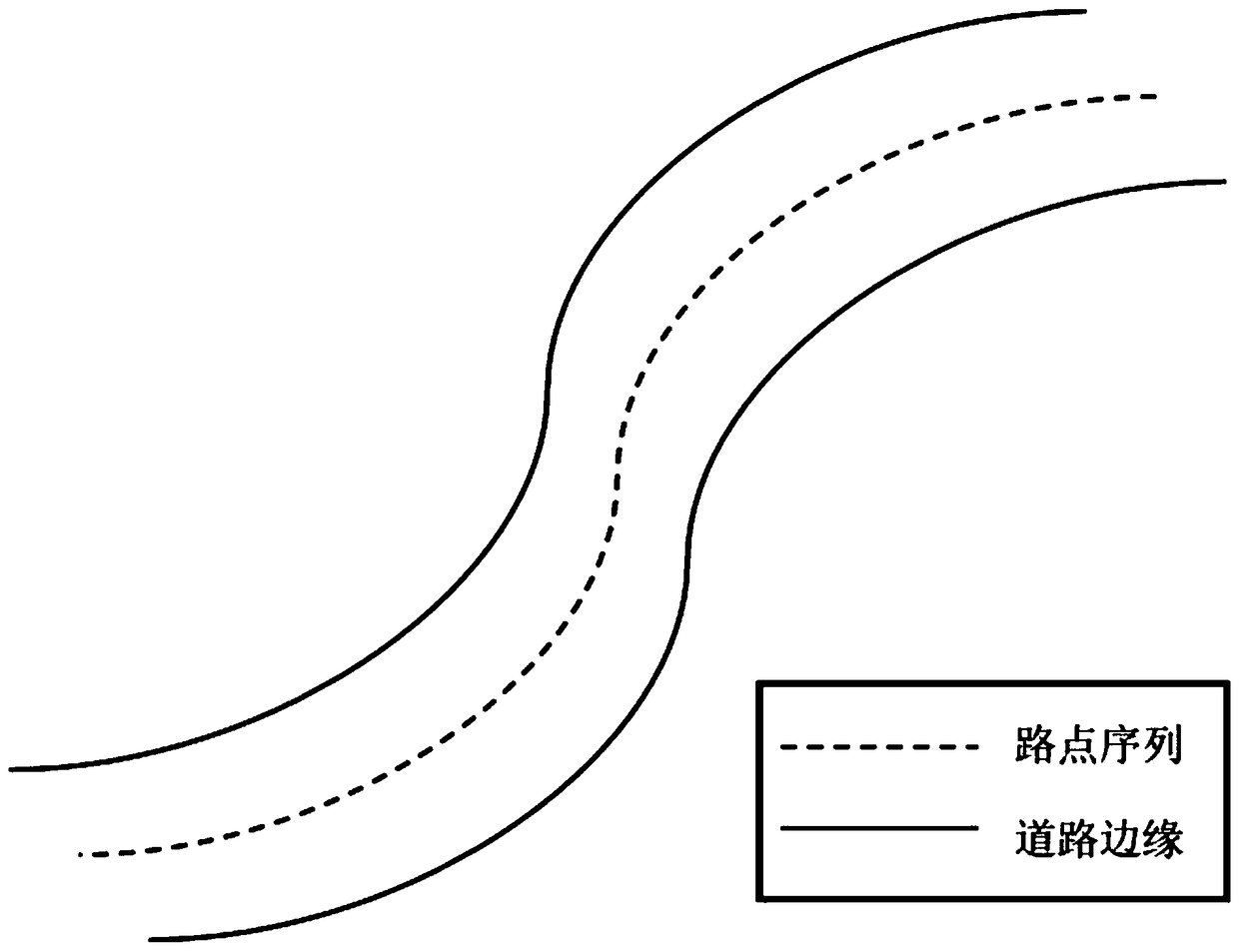
[0038] Such as figure 1 , 2 As shown, step 100 is executed, and the acquisition module 200 is used to acquire sensor information. Acquire the waypoint sequence P that guides the unmanned vehicle's forward route containing spatial position information through the sensor installed on the unmanned vehicle at the site i , waypoint information such as image 3 As shown, the field unmanned vehicle is equipped with a dual-antenna positioning and directional receiver. Execute step 110, carry out global waypoint coordinate transformation, comprise: first carry out map file parsing, then WGS-84 coordinate (World GeodeticSystem-1984 Coordinate System) of GPS is converted into the plane coordinate described by UTM coordinate (Universal Transverse Mercator), then Transform the global coordinates into local coordinates with the particle of the unmanned vehicle as the coordinate origin. Execute step 120, execute step 120, use the fitting module 210 to carry out high-order Bezier curve fi...
Embodiment 2
[0040] Such as figure 1 , 2 As shown, step 100 is executed, and the acquisition module 200 is used to acquire sensor information. A Velodyne 16-line laser radar is installed on the central position of the front of the unmanned vehicle on the site, and the waypoint sequence P that guides the unmanned vehicle's forward route including spatial position information is obtained through the sensor installed on the unmanned vehicle on the site. i , waypoint information such as image 3 shown. Step 110 is executed to perform global waypoint coordinate conversion, including: first analyzing the lidar SLAM map file, and then converting the global coordinates into local coordinates with the mass point of the unmanned vehicle as the coordinate origin. Execute step 120, use the fitting module 210 to perform high-order Bezier curve fitting on the obtained waypoint sequence to obtain the trajectory line, and the calculation formula is Among them, B(t) is the path after high-order Bezier...
Embodiment 3
[0042] Such as figure 1 , 2 As shown, step 100 is executed, and the acquisition module 200 is used to acquire sensor information. A vehicle-mounted monocular camera is arranged on the central position of the head of the unmanned vehicle on the site, and the waypoint sequence P that guides the unmanned vehicle's forward route containing spatial position information is obtained through the sensor installed on the unmanned vehicle on the site. i , waypoint information such as image 3 shown. Execute step 110 to perform global waypoint coordinate conversion, including: first analyze the image SLAM map file, and then convert the global coordinates into local coordinates with the mass point of the unmanned vehicle as the coordinate origin. Execute step 120, use the fitting module 210 to perform high-order Bezier curve fitting on the obtained waypoint sequence to obtain the trajectory line, and the calculation formula is Among them, B(t) is the path after high-order Bezier curve...
PUM
 Abstract
Description
Claims
Application Information