Low-beam radar-based optimal detection method and device for low obstacles

A detection method and obstacle technology, applied in image data processing, instrument, character and pattern recognition, etc., can solve problems such as limiting the stable recognition range and recognition effect of laser radar, achieve fast computing speed, good real-time performance, and reduce leakage Check the effect

Active Publication Date: 2018-10-12
BEIJING INSTITUTE OF TECHNOLOGYGY
View PDF6 Cites 18 Cited by
  • Summary
  • Abstract
  • Description
  • Claims
  • Application Information

AI Technical Summary

Problems solved by technology

Therefore, the point cloud with too few scans in a single frame l

Method used


Image

  • Low-beam radar-based optimal detection method and device for low obstacles
  • Low-beam radar-based optimal detection method and device for low obstacles
  • Low-beam radar-based optimal detection method and device for low obstacles

Examples


Example Embodiment

[0026] The present invention will be described in detail below with reference to the drawings and embodiments.

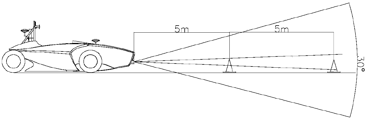
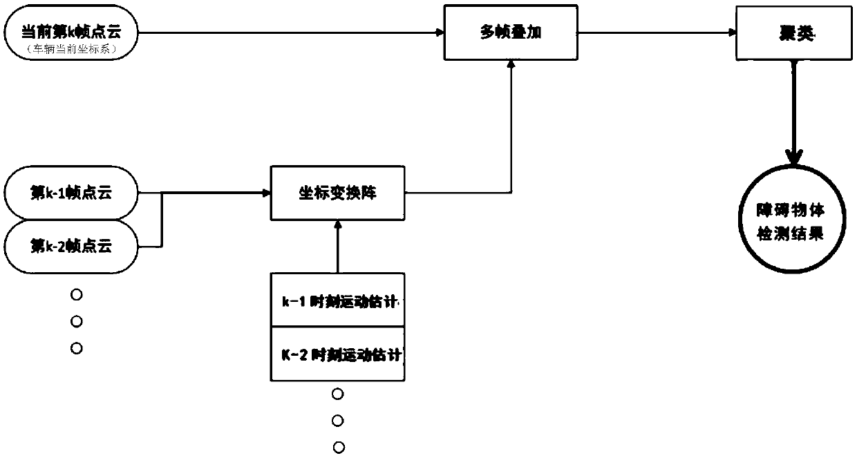
[0027] The invention provides an optimized detection method and device for low obstacles based on low beam radar, which can improve the effective recognition of low obstacles by lidar, strengthen the recognition effect, and reduce the influence of noise points. The invention belongs to the field of photoelectric information and computer technology, and has a promoting effect on the technology of unmanned vehicles. Such as figure 1 As shown, when the distance between the two vertical lines of the lidar at 10 meters can reach the height of a 30cm cone, there is sometimes no recognition instability. The core of the multi-frame point cloud superposition algorithm proposed by the present invention is to convert historical point cloud data into the current frame lidar coordinate system through motion estimation, and superimpose it into the current frame point cloud data, the...


PUM


Abstract

The invention provides a low-beam radar-based optimal detection method and device for low obstacles. According to the core of the method, historical point cloud data are converted into a laser radar coordinate system of the current frame through motion estimation and superimposed into point cloud data of the current frame to fuse historical information, so that the effective identification of laser radar on the low obstacles is improved, the identification effect is enhanced and the influence of noise points is reduced.

Description

technical field [0001] The invention belongs to the technical field of optoelectronic information and computers, and in particular relates to an optimized detection method and device for low-slung obstacles based on low-wire beam radar, which can be widely used in perception systems of unmanned vehicles and robots. Background technique [0002] At present, with the development and continuous improvement of hardware and software involved in unmanned driving technology, the unmanned driving industry will continue to mature and land. In order to reduce costs, low-line lidar is widely used. For the vast majority of recognized objects such as vehicles, pedestrians and street signs, low-line-count radar can be accurately recognized. However, when low-line laser radar scans low objects on the road such as curbstones, scattered objects, etc., due to the low vertical angular resolution, usually only one line can be scanned for distant obstacles, and with the radar relative It is ea...

Claims


Application Information

Patent Timeline
IPC IPC(8): G06K9/00G06T7/246
CPCG06T7/248G06T2207/10028G06T2207/30261G06V20/58
Inventor 倪俊胡纪滨田汉青潘博赵越李云霄田戴莹张乃斯马宁刘庆霄
Owner BEIJING INSTITUTE OF TECHNOLOGYGY
Why Eureka
Try Eureka