Electrically-controlled auxiliary type nail hammering striking device

A hammer and electronic control technology, applied in the field of electronically controlled auxiliary hammer hammering device, can solve the problems of easy shaking, inability to achieve, trouble, etc., and achieve the effect of high-efficiency hammering auxiliary function, wide applicability, and guaranteeing stability.

Inactive Publication Date: 2018-10-16
苏州诺登德智能科技有限公司
View PDF7 Cites 2 Cited by
  • Summary
  • Abstract
  • Description
  • Claims
  • Application Information

AI Technical Summary

Problems solved by technology

[0002] The nail hammer is the most common and common tool in machinery. In actual use of the nail hammer, the operator holds the nail with his fingers in one hand and stands it at the designated position, and holds the nail hammer in the other hand to hit the top of the nail to achieve the nail to the designated position. It can be seen that the operator needs to hold the nail to maintain the posture of nailing in the specified direction, but if encountering a relatively narrow space, the operation of maintaining the nail posture becomes very troublesome. , or even impossible to achieve, and if the extension rod is used for hitting, the contact position between the extension rod and the top of the nail is in an unstable state, and it is prone to shaking, that is, the posture of the nail cannot be maintained. Therefore, the existing technology is for special space The operation of the hammer under the hammer still needs to be improved and improved.

Method used


Image

  • Electrically-controlled auxiliary type nail hammering striking device

Examples


Embodiment Construction

[0024] The specific embodiments of the present invention will be described in further detail below in conjunction with the accompanying drawings of the specification.

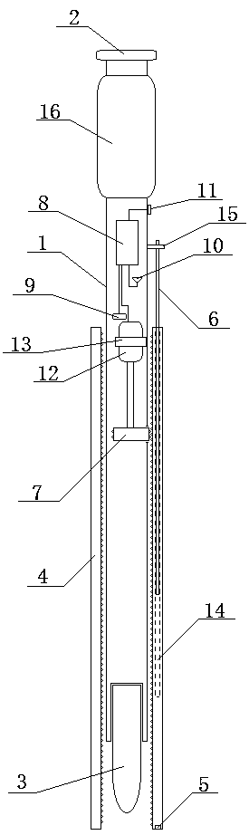
[0025] Such as figure 1 As shown, the present invention designs an electronically controlled assisted nail hammer striking device, which includes the extension rod body 1, the striking end cover 2, the magnetic striking body part 3, the clamping sleeve 4, the wireless ranging sensor 5, and the limiter. Position rod 6, drive disk 7 and control module 8, as well as power supply 9, wireless signal transceiver 10, control button 11, and rotating motor 12 respectively connected to control module 8. Among them, power supply 9 is a wireless signal through control module 8 The transceiver 10, the control button 11, and the rotating motor 12 are powered, and the wireless ranging sensor 5 uses self-powered power; the center line of the extension rod body 1 is a straight line, and the outer diameter of the striking end cap 2...


PUM


Abstract

The invention relates to an electrically-controlled auxiliary type nail hammering striking device. A clamping position sleeve (4) structure is introduced on the basis of an extension rod body (1) by adopting the electrically-controlled propelling mechanical structure design, driving rotating is conducted on a driving disc (7) of which the edge protrudes out of the outer wall of the extension rod body (1) by combining with a rotating motor (12), the purpose that the clamping position sleeve (4) moves along the outer wall of the extension rod body (1) back and forth is achieved under rotating limiting of a limiting rod (6) on the clamping position sleeve (4), sleeving clamping is achieved for nails struck by a magnetic striking body part (3) arranged on the extension rod body (1), and the stability of the nail posture is guaranteed. According to the electrically-controlled auxiliary type nail hammering striking device, the distance between the bottom end of the clamping position sleeve (4) and the plane where the nails are arranged is detected in real time through a wireless distance measuring sensor (5), the rotating motor (12) is intelligently controlled on this basis, automatic moving of the clamping position sleeve (4) is achieved in real time in the nail hammering process, and the stability of the nail posture is effectively guaranteed.

Description

Technical field [0001] The invention relates to an electronically controlled auxiliary nail hammer striking device, which belongs to the technical field of mechanical tools. Background technique [0002] Mace is the most common and common tool in machinery. In actual use, the operator holds the nail with his fingers and stands it at the designated position, and the other hand holds the nail hammer to hit the top of the nail to achieve the nail to the designated position It can be seen that the operator needs to hold the nail and maintain the posture of the nail in the specified direction. However, if a relatively narrow space is encountered, the operation of maintaining the nail posture becomes very troublesome. , It can’t even be achieved, and if the extension rod is used to strike, the contact position between the extension rod and the top of the nail is in an unstable state, and it is prone to shaking, that is, the nail’s posture cannot be maintained. Therefore, the prior art ...

Claims


Application Information

Patent Timeline
Patent Type & Authority Applications(China)
IPC IPC(8): B25C1/06B25C3/00
CPCB25C1/06B25C3/008
Inventor 马峻徐企娟
Owner 苏州诺登德智能科技有限公司
Why Eureka
Try Eureka