A joint grout stop device for steel-concrete combined section and its construction method

A steel-concrete combination and construction method technology, which is applied in the erection/assembly of bridges, buildings, bridge construction, etc., can solve the problem that the slurry stop method cannot be extended, and achieve strong overall slurry resistance, improved stability, and convenient construction. Effect

Active Publication Date: 2020-07-28
JIANGSU PROVINGIAL TRANSPORTATION ENG GRP
View PDF7 Cites 0 Cited by
  • Summary
  • Abstract
  • Description
  • Claims
  • Application Information

AI Technical Summary

Problems solved by technology

However, due to the requirements of the construction technology, when installing the steel structure of the steel-concrete joint section, the hanging basket and the side formwork have been removed. slurry method

Method used


Image

  • A joint grout stop device for steel-concrete combined section and its construction method

Examples


Embodiment 1

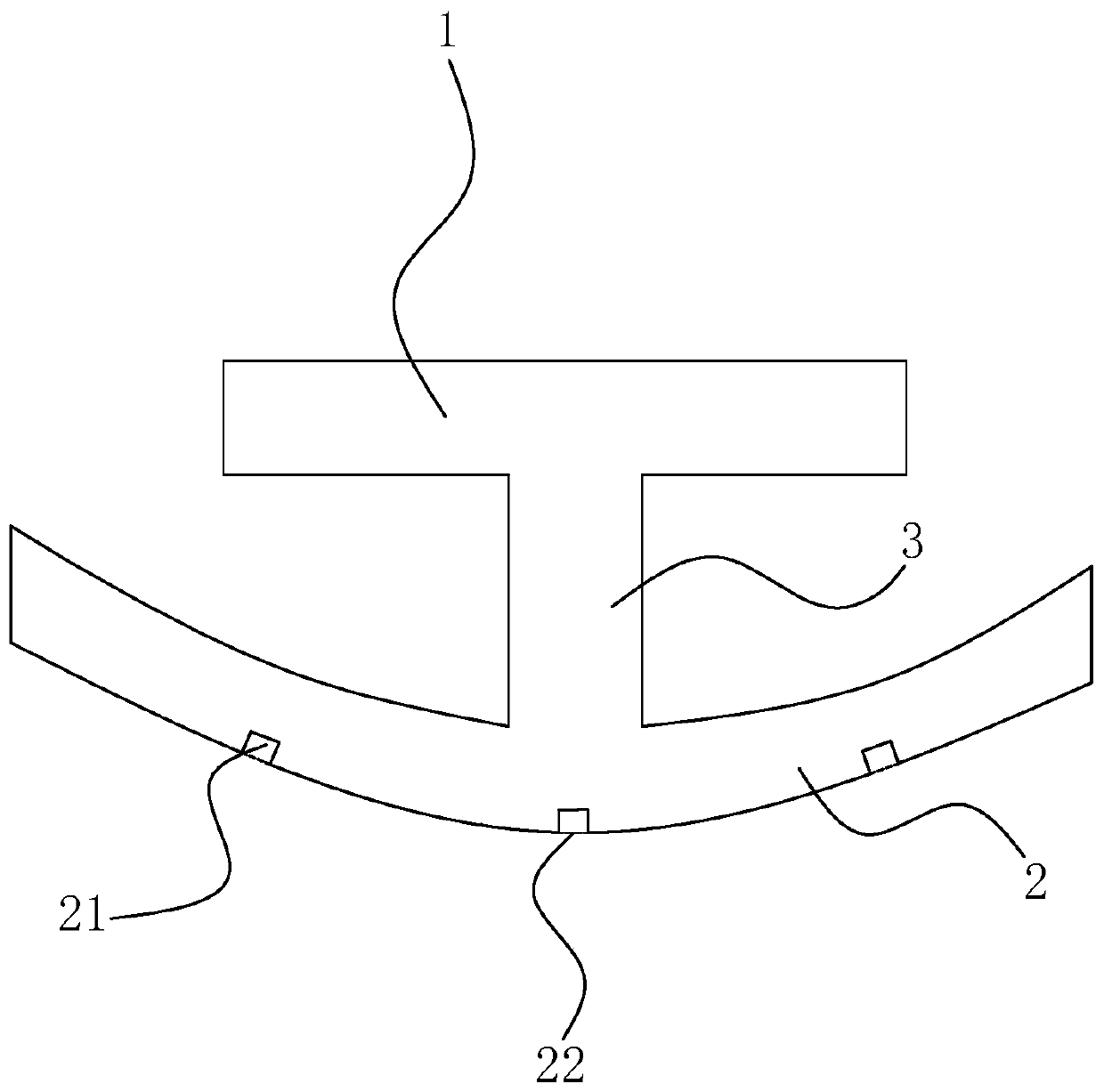
[0043] A joint grout stop device for a steel-concrete joint section, such as figure 1As shown, when the steel structure of the steel-concrete joint section is installed, the hanging basket and the side formwork have been removed, including the upper wing plate 1, and the lower wing plate 2 is arranged in parallel below the upper wing plate 1, and the upper wing plate 1 and The center of the lower wing plate 2 is connected with a vertical support plate 3, so that the entire seam stopper is I-shaped. At the same time, the lower wing plate 2 is U-shaped, with the opening facing the upper wing plate 1, and is made of polyurethane water-swellable elastic waterproof material. This type of material not only has elasticity and extensibility similar to rubber, but also The performance of expansion has the effects of elasticity, waterproof, sealing and anti-sizing, so that it can not only save the amount of materials, but also eliminate the shortcomings of elastic fatigue and abrasion a...

Embodiment 2

[0049] A construction method applied to embodiment 1, comprising the following steps:

[0050] S1. By installing a laser transmitter and a receiving board at the interface of the steel-concrete joint section on both sides, the bottom of the laser transmitter is equipped with a slide rail flush with the joint, and the receiving board on the other side is at the same level as the interface. In the plane, adjust the position of the laser transmitter on the slide rail so that the light emitted by the laser transmitter is irradiated on the center of the receiving plate, so as to obtain the actual connection between the steel box girder and the overhanging block in the on-site steel-concrete joint section. Seam distance;

[0051] S2, select the width of upper wing plate 1 and lower wing plate 2 according to the distance measured by S1, make the width of upper wing plate 1 increase 50-60cm on the basis of the measured distance, so that the upper wing plate 1 on the seam surface is su...

Embodiment 3

[0057] A construction method applied to embodiment 1, comprising the following steps:

[0058] S1. By installing a laser transmitter and a receiving board at the interface of the steel-concrete joint section on both sides, the bottom of the laser transmitter is equipped with a slide rail flush with the joint, and the receiving board on the other side is at the same level as the interface. In the plane, adjust the position of the laser transmitter on the slide rail so that the light emitted by the laser transmitter is irradiated on the center of the receiving plate, so as to obtain the actual connection between the steel box girder and the overhanging block in the on-site steel-concrete joint section. Seam distance;

[0059] S2. Select the width of the upper wing plate 1 and the lower wing plate 2 according to the distance measured by S1, so that the width of the upper wing plate 1 is increased by 55 cm on the basis of the measured distance, so that the force of the upper wing ...


PUM


Abstract

The invention discloses a joint grouting-stopping device for a steel-concrete combined section and a construction method thereof, and relates to the technical field of joint grouting-stopping construction. The joint grouting-stopping device for the steel-concrete combined section and the construction method thereof aim at solving the problem that when a steel structure of the steel-concrete combined section is mounted, a hanging basket and a side formwork are both dismantled, and no good grouting-stopping measure is set to ensure the concrete construction quality. According to the technical key points, the joint grouting-stopping device comprises an upper wing plate; a lower wing plate is arranged below the upper wing plate parallelly, the centers of the upper wing plate and the lower wingplate are connected with a vertically-arranged supporting plate, the lower wing plate is in a U shape, and an opening of the lower wing plate faces the upper wing plate; and the lower wing plate is formed by manufacturing and machining a polyurethane-type water swelling elastic waterproof material. During construction, the supporting plate and the lower wing plate are clamped into the joint, thenthe upper wing plate is fixed to the two sides of the joint, the lower wing plate is bent towards the upper wing plate under the action of the downward pressing force to closely abut against the twoside walls of the joint, and accordingly the grouting-stopping effect can also be ensured while construction is facilitated.

Description

technical field [0001] The invention relates to the technical field of joint grouting construction, in particular to a joint grouting device for a steel-concrete joint section and a construction method thereof. Background technique [0002] The steel-concrete structure is a mixed structure of steel and concrete, including the frame-core tube structure composed of the peripheral steel frame or steel concrete, steel tube concrete frame and reinforced concrete core tube, and the peripheral steel frame tube or steel concrete, steel tube concrete frame tube A tube-in-tube structure composed of a reinforced concrete core tube. [0003] At present, in order to prevent the joint grouting of the hanging construction of the express hanging basket of the long-span continuous steel-concrete mixed girder bridge, one end of the side form of the hanging basket is usually covered on the surface of the poured block concrete, and then passed through the poured block. The reserved holes on th...

Claims


Application Information

Patent Timeline
Patent Type & Authority Patents(China)
IPC IPC(8): E01D21/00E01D19/00
CPCE01D19/00E01D21/00
Inventor 巫亚明季广国
Owner JIANGSU PROVINGIAL TRANSPORTATION ENG GRP
Why Eureka
Try Eureka