Joint grouting-stopping device for steel-concrete combined section and construction method thereof
A steel-concrete combination and construction method technology, which is applied in the direction of erecting/assembling bridges, bridge parts, bridges, etc., can solve the problems such as the inability to continue to use the grout stop method, and achieve the overall strong grout stop performance, high work efficiency and convenient construction Effect
- Summary
- Abstract
- Description
- Claims
- Application Information
AI Technical Summary
Problems solved by technology
Method used
Image
Examples
Embodiment 1
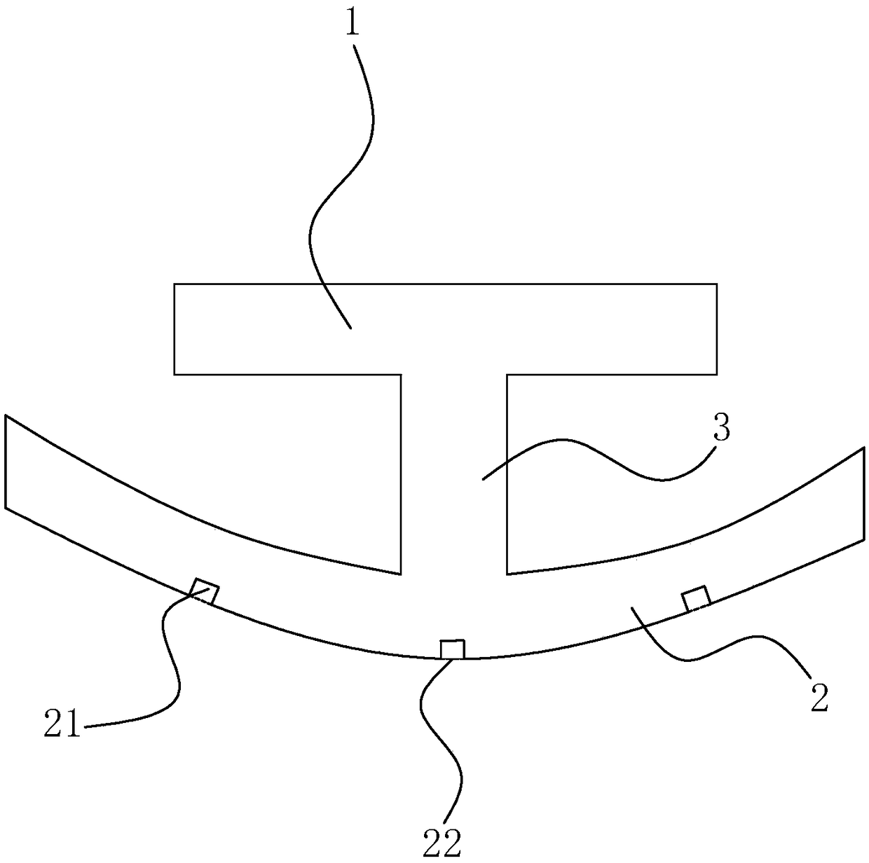
[0043] A joint grout stop device for a steel-concrete joint section, such as figure 1As shown, when the steel structure of the steel-concrete joint section is installed, the hanging basket and the side formwork have been removed, including the upper wing plate 1, and the lower wing plate 2 is arranged in parallel below the upper wing plate 1, and the upper wing plate 1 and The center of the lower wing plate 2 is connected with a vertical support plate 3, so that the entire seam stopper is I-shaped. At the same time, the lower wing plate 2 is U-shaped, with the opening facing the upper wing plate 1, and is made of polyurethane water-swellable elastic waterproof material. This type of material not only has elasticity and extensibility similar to rubber, but also The performance of expansion has the effects of elasticity, waterproof, sealing and anti-sizing, so that it can not only save the amount of materials, but also eliminate the shortcomings of elastic fatigue and abrasion a...
Embodiment 2
[0049] A construction method applied to embodiment 1, comprising the following steps:
[0050] S1. By installing a laser transmitter and a receiving board at the interface of the steel-concrete joint section on both sides, the bottom of the laser transmitter is equipped with a slide rail flush with the joint, and the receiving board on the other side is at the same level as the interface. In the plane, adjust the position of the laser transmitter on the slide rail so that the light emitted by the laser transmitter is irradiated on the center of the receiving plate, so as to obtain the actual connection between the steel box girder and the overhanging block in the on-site steel-concrete joint section. Seam distance;
[0051] S2, select the width of upper wing plate 1 and lower wing plate 2 according to the distance measured by S1, make the width of upper wing plate 1 increase 50-60cm on the basis of the measured distance, so that the upper wing plate 1 on the seam surface is su...
Embodiment 3
[0057] A construction method applied to embodiment 1, comprising the following steps:
[0058] S1. By installing a laser transmitter and a receiving board at the interface of the steel-concrete joint section on both sides, the bottom of the laser transmitter is equipped with a slide rail flush with the joint, and the receiving board on the other side is at the same level as the interface. In the plane, adjust the position of the laser transmitter on the slide rail so that the light emitted by the laser transmitter is irradiated on the center of the receiving plate, so as to obtain the actual connection between the steel box girder and the overhanging block in the on-site steel-concrete joint section. Seam distance;
[0059] S2. Select the width of the upper wing plate 1 and the lower wing plate 2 according to the distance measured by S1, so that the width of the upper wing plate 1 is increased by 55 cm on the basis of the measured distance, so that the force of the upper wing ...
PUM
 Abstract
Description
Claims
Application Information
 - R&D
- Intellectual Property
- Life Sciences
- Materials
- Tech Scout
- Unparalleled Data Quality
- Higher Quality Content
- 60% Fewer Hallucinations
Browse by: Latest US Patents, China's latest patents, Technical Efficacy Thesaurus, Application Domain, Technology Topic, Popular Technical Reports.
© 2025 PatSnap. All rights reserved.Legal|Privacy policy|Modern Slavery Act Transparency Statement|Sitemap|About US| Contact US: help@patsnap.com

