
Phase-change cold storage air-conditioning control room

A phase-change cold storage and computer room technology, which is applied in air conditioning systems, mechanical equipment, space heating and ventilation, etc., can solve the problems of ignoring the comprehensive energy efficiency of the computer room, long-term operation of the system with diseases, and no start-up strategy, etc., and achieves a significant effect of cold storage , Improve energy efficiency, improve the effect of environmental comfort

Pending Publication Date: 2018-10-16
DONGGUAN ZHAORONG ENERGY SAVING SCI & TECH
View PDF2 Cites 0 Cited by
  • Summary
  • Abstract
  • Description
  • Claims
  • Application Information

AI Technical Summary

Problems solved by technology

[0005] The current air-conditioning machine room lacks accurate detection of the operating status of the above four major equipment, and implements extensive management of equipment operation; or does not formulate a start-up strategy that can keep the main engine running efficiently according to the change of terminal load, or the control means are limited and cannot be effective Execution; or the system debugging is not in place, and the defects are not eliminated, causing the system to run for a long time with a disease; the industry standard pays attention to the energy efficiency of the main engine, and ignores the comprehensive energy efficiency of the computer room

Method used


Image

  • Phase-change cold storage air-conditioning control room
  • Phase-change cold storage air-conditioning control room
  • Phase-change cold storage air-conditioning control room

Examples


Embodiment 1

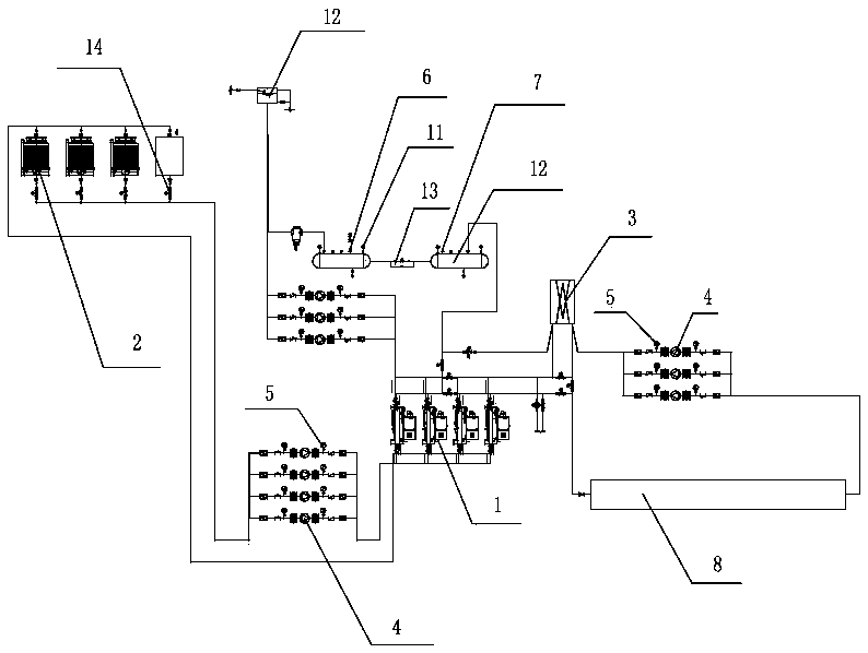
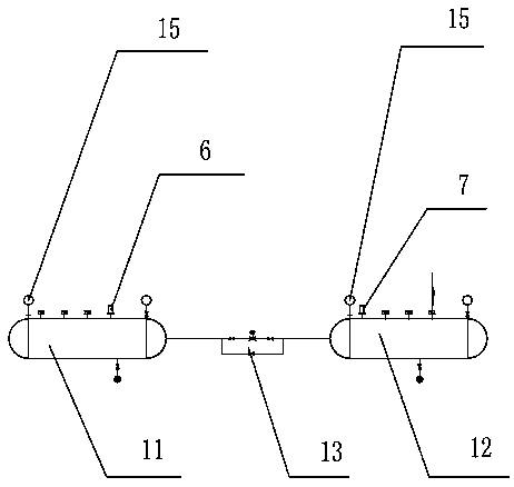
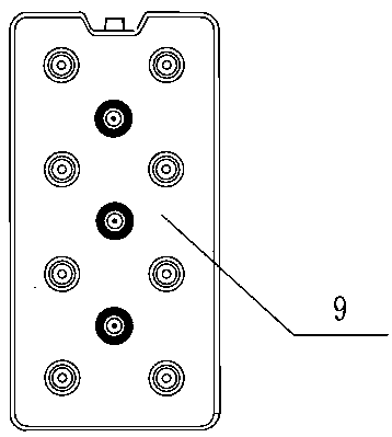
[0032] Embodiment 1, refer to attached figure 1 , attached figure 2 , attached image 3 :

[0033] A phase-change cold storage air conditioner room, including a refrigeration system composed of 4 refrigerators 1 connected in parallel, a heat exchange system 3 composed of 2 heat exchangers, a cooling system composed of 4 cooling water towers 2, and a cold storage system composed of 3 cold storage tanks 8 In the system, four one-way valves 4 and eight temperature sensors 5 are arranged between the refrigerator 1 and the cooling water tower 2, the temperature sensors 5 are located on both sides of the single valve 4, the refrigerator 1 and the cold storage tank 8 are connected in parallel to the heat exchanger, The heat exchanger is located in the machine room. The cold storage tank 8 and the cooling water tower 2 are connected in parallel to the refrigerator 1. Three check valves 4 and six temperature sensors 5 are arranged between the cold storage tank 8 and the heat exchan...


PUM


Abstract

The invention provides a phase-change cold storage air-conditioning control room which comprises a refrigerating system, a cooling system, a heat exchange system, a cold storage system and a control system, wherein the cold storage system and the refrigerating system are connected to a central control system; the cooling system and the refrigerating system are provided with one-way valve systems and temperature sensors; one-way valve systems and temperature sensors are arranged between the cold storage system and the refrigerating system; the refrigerating system and the cold storage system are connected to the heat exchange system in parallel; the heat exchange system is located at the tail end of a load; the refrigerating system comprises 1-10 parallel refrigerators; the cooling system comprises 1-10 cooling water towers; the cold storage system comprises 1-10 phase-change cold storage tanks; and the heat exchange system comprises 1-8 heat exchangers which are connected in parallel or in series or in series-parallel connection. The electricity consumption in a peak electric stage can be transferred; the refrigerating capacity at the peak of the existing system is increased; the benefit of a chilled water unit is increased; control of a chilled water system is increased; the service life of the chilled water system is prolonged; the reliability of the chilled water system is improved; the operating elasticity of the chilled water system is improved; the utilization efficiency of energy sources is improved in part of on-load operations of a refrigerating unit, the electricpower is saved by 30-50%, and the electric charge is saved by 40-70%.

Description

technical field [0001] The invention belongs to the technical field of air conditioning cold storage and energy saving, and in particular relates to a phase change cold storage air conditioner room. Background technique [0002] With the popularity of air-conditioning, the proportion of electricity consumed by air-conditioning in building energy consumption is gradually increasing. In summer, the energy consumption of air-conditioning accounts for 85% of building energy consumption, which makes the peak-to-valley difference in electricity use larger, and there is a phenomenon that electricity demand exceeds supply during peak periods of electricity consumption, and excess electricity consumption occurs during low-peak periods of electricity consumption. Moreover, because the country has introduced a power policy that encourages peak shifting and valley filling to make full use of power resources, cold storage air conditioners are therefore favored by people. [0003] The so...

Claims


Application Information

Patent Timeline
IPC IPC(8): F24F5/00F24F13/30F24F11/84F24F11/89C09K5/06
CPCF24F5/0021F24F11/84F24F11/89F24F13/30C09K5/063F24F2005/0032Y02E60/14Y02P20/10
Inventor 许加潭李国荣
Owner DONGGUAN ZHAORONG ENERGY SAVING SCI & TECH
Learn More