
Small lens detecting device and detecting method thereof

A lens detection and detection method technology, applied in the direction of testing optical performance, etc., can solve the problems affecting the production speed of the lens, slow running speed, slow speed, etc., and achieve the effect of improving the production efficiency of the lens, fast measurement, and simple measurement principle.

Inactive Publication Date: 2018-10-16
北京全欧光学检测仪器有限公司
View PDF7 Cites 10 Cited by
  • Summary
  • Abstract
  • Description
  • Claims
  • Application Information

AI Technical Summary

Problems solved by technology

However, one limitation of the existing equipment (focal length meter and center deviation measuring instrument) is that the operating speed is slow, which affects the production speed of the lens. The center deviation measuring instrument generally needs to rotate the lens under test to measure the eccentricity error, and the speed is relatively slow.

Method used


Image

  • Small lens detecting device and detecting method thereof
  • Small lens detecting device and detecting method thereof
  • Small lens detecting device and detecting method thereof

Examples


Embodiment Construction

[0046] The embodiments of the present invention are described in detail below. This embodiment is implemented on the premise of the technical solution of the present invention, and detailed implementation methods and specific operating procedures are provided, but the protection scope of the present invention is not limited to the following implementation example.

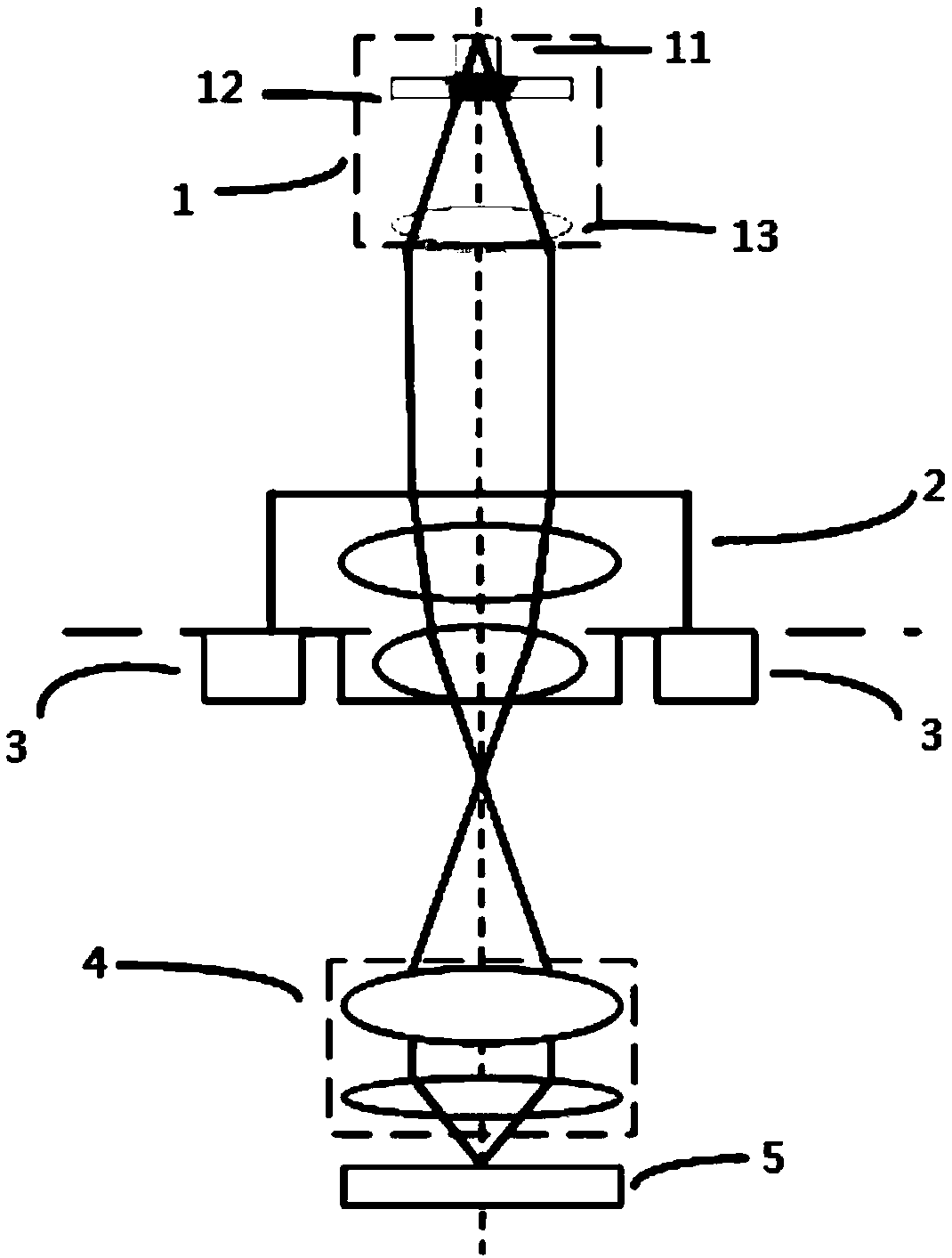
[0047] combine figure 1 , describe in detail the preferred embodiment of the small lens detection device of the present invention, as figure 1As shown, it includes: a light source system 1, an objective lens group 4 and an image receiver 5; wherein, the light source system 1, the objective lens group 4 and the image receiver 5 are arranged in sequence, and the lens 2 to be tested is located between the light source system 1 and the objective lens group between 4; the light source system 1, the lens to be tested 2, the objective lens group 4 and the image receiver 5 are located on the same mechanical central axis; ...


PUM


Abstract

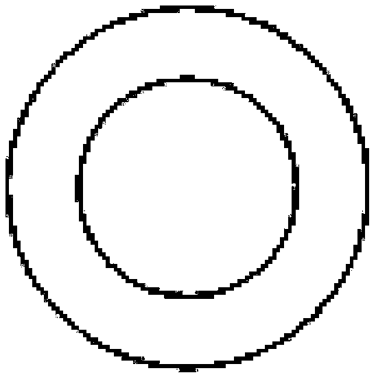
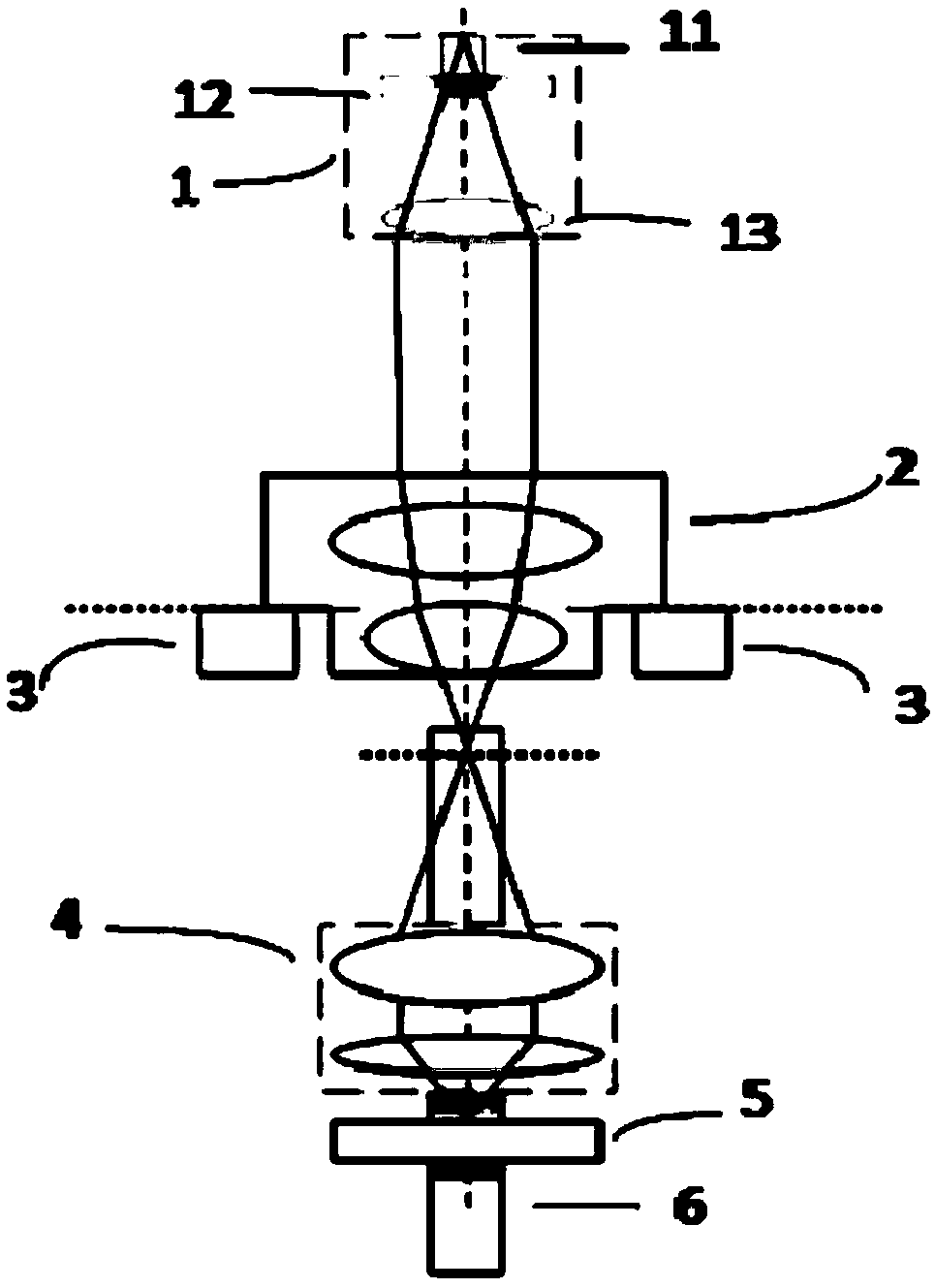
The invention discloses a small lens detecting device and a detecting method thereof. The device comprises a light source system, an object lens group and an image receiving device which are sequentially arranged; a to-be-detected lens is located between the light source system and the object lens group; the light source system, the to-be-detected lens, the object lens group and the image receiving device are located on the same mechanical central shaft; the light source system comprises a point light source, a dividing plate and a collimation lens which are sequentially arranged; the point light source is located on the focal distance position of the collimation lens; the dividing plate is arranged close to the point light source; the object lens group comprises a first part and a secondpart; the object lens group is fixed opposite to the image receiving device at interval, and the object lens group and the image receiving device can be moved upwards together in the direction of themechanical shaft. The method comprises the steps of effective focal distance measurement, and / or flange focal distance measurement, and / or eccentric error measurement. The device and the method has the advantages of simple measuring principle, simple structure, low cost, high operating speed and high measuring precision.

Description

technical field [0001] The invention relates to the field of lens detection, in particular to a small lens detection device and a detection method thereof. Background technique [0002] In recent years, with the vigorous development of the consumer electronics industry, various types of small optical lenses (small lens diameters less than 10mm) have been used more and more, and the shipments of small lenses for mobile phones, security and vehicles have increased year by year. Performance requirements are also getting higher and higher. [0003] Usually the performance test parameters of the lens include optical transfer function, effective focal length, flange focal length and eccentricity error, etc., and judge whether the lens is qualified according to these parameters. Due to the huge annual shipments of small lenses, the corresponding number of lenses to be tested is also very large, so the test lens equipment is required to run fast and have high measurement accuracy. ...

Claims


Application Information

Patent Timeline
IPC IPC(8): G01M11/02
CPCG01M11/02
Inventor 田贺斌何志远
Owner 北京全欧光学检测仪器有限公司
Learn More