Device for detecting small defect of pipeline and method for detecting center and diameter of defect
A detection device and defect center technology, which is applied in the field of pipeline detection, can solve the problems of low detection sensitivity of small defects, and achieve the effects of shortening the detection cycle, improving maintenance efficiency, and improving accuracy
- Summary
- Abstract
- Description
- Claims
- Application Information
AI Technical Summary
Problems solved by technology
Method used
Image

Examples
Embodiment 1
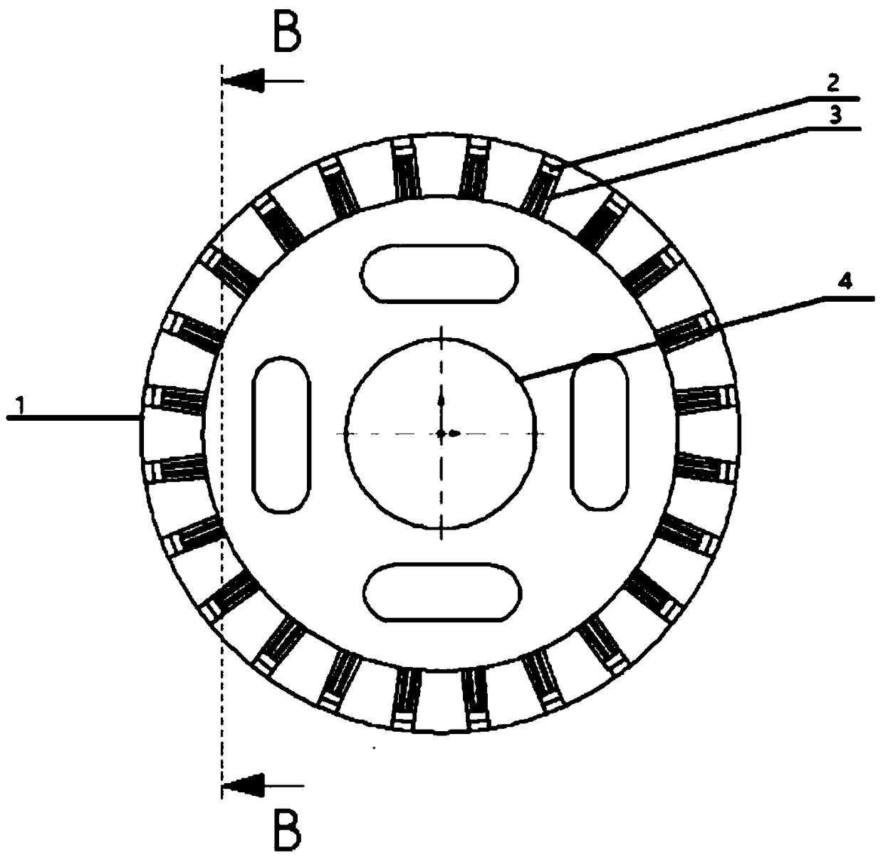
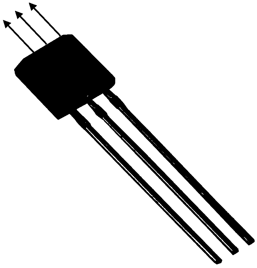
[0048] A detection device for tiny defects in pipelines, see Figure 1-Figure 5 , the detection device includes: a detector 1 in the pipeline, a Hall element 2 and a magnet 5 are installed on the detector 1 in the pipeline (the embodiment of the present invention takes a cylindrical magnet 5 as an example for illustration, and during specific implementation, the embodiment of the present invention This is not limited), the model of the Hall element 2 used in this detection device is SS495A1, it has three pins, and its physical figure is as follows figure 2 shown.
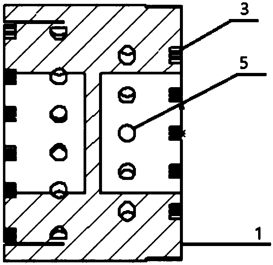
[0049] The front view and cross-sectional view of the detector 1 in the pipeline are as follows figure 1 and image 3 As shown: In order to avoid short circuit, each Hall element 2 is equipped with three pin slots 3 to respectively place the above three pins.
[0050] Such as image 3 As shown, the circular hole on the inner wall of the detector 1 in the pipeline is used to place a cylindrical magnet 5, and the H...
Embodiment 2
[0053] The scheme in embodiment 1 is explained in principle below in combination with specific numerical values, see the following description for details:
[0054] The schematic diagram of the experimental device for the steel pipe test is shown in Figure 4 As shown: the detector 1 in the pipeline needs to be pushed forward by the pipeline fluid 13, and the wall of the device is attached to the wall of the pipeline.
[0055] In the in-pipe detector 1, the circumferential distance between the Hall elements 2 is 10-20mm, and the radius of the in-pipe detector 1 is equal to the inner diameter of the pipe.
[0056] The system block diagram of the detection device is as follows Figure 5 As shown: the battery 6 supplies power to the power management module 7, and the power supply to the Hall element 2 and the single-chip microcomputer 9 is realized through the power management module 7;
[0057] When the body of the pipeline detector 1 moves smoothly in the pipeline 11, under t...
Embodiment 3
[0063] A detection method for the center and diameter of pipeline tiny defects, see Figure 6 and Figure 7 , the detection method includes:
[0064] first to Figure 6 and Figure 7 The obtained magnetic field characteristic signal curve is analyzed, and the magnetic field characteristic signal curve is analyzed, and the place with obvious depression is called a trough;
[0065] Identify the trough C in the magnetic field characteristic signal curve, and the amplitude corresponding to the trough C is H; then find two points A and B whose corresponding amplitudes are h1 and h2 respectively, where Record the time t corresponding to A and B respectively 1 and t 2 and the time t corresponding to the trough C 3 , denoting the moving speed of the detector in the pipeline as v, then:
[0066] The position of the center of the tiny defect in the pipeline = v*t 3 ;
[0067] Diameter of tiny defect in pipeline = k*(t 2 -t 1 )*v; among them, k needs to be calibrated in advan...
PUM
 Abstract
Description
Claims
Application Information
 - R&D
- Intellectual Property
- Life Sciences
- Materials
- Tech Scout
- Unparalleled Data Quality
- Higher Quality Content
- 60% Fewer Hallucinations
Browse by: Latest US Patents, China's latest patents, Technical Efficacy Thesaurus, Application Domain, Technology Topic, Popular Technical Reports.
© 2025 PatSnap. All rights reserved.Legal|Privacy policy|Modern Slavery Act Transparency Statement|Sitemap|About US| Contact US: help@patsnap.com