Coil assembly structure and magnetoelectric crankshaft speed sensor

A technology of coil components and coils, applied in coils, transformers/inductor coils/windings/connections, circuits, etc., can solve problems such as impracticality, increased process difficulty and cost, to prevent product failure, reduce the risk of mechanical damage, The effect of increasing the distance

Pending Publication Date: 2018-10-16
SHENZHEN SENSOR TECH CO LTD
View PDF0 Cites 2 Cited by
  • Summary
  • Abstract
  • Description
  • Claims
  • Application Information

AI Technical Summary

Problems solved by technology

However, this method is not practical in the production process of automatic winding equipment, which increases the difficulty and cost of the process

Method used


Image

  • Coil assembly structure and magnetoelectric crankshaft speed sensor
  • Coil assembly structure and magnetoelectric crankshaft speed sensor
  • Coil assembly structure and magnetoelectric crankshaft speed sensor

Examples


Embodiment Construction

[0030] The embodiments of the present invention will be described in detail below. It should be emphasized that the following description is only exemplary, and is not intended to limit the scope of the present invention and its application.

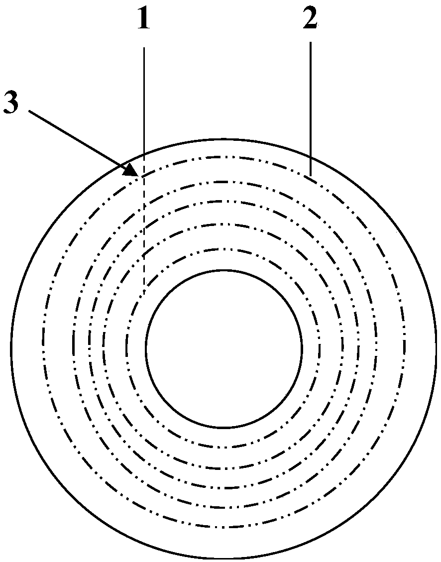
[0031] See image 3 In one embodiment, a coil assembly structure includes a coil bobbin 6 and a coil 7. The coil bobbin 6 has a winding groove 5, and the coil 7 is wound in the winding groove of the coil bobbin 6. In 5, the side wall of the winding groove 5 is provided with a lead groove 4 recessed to the outside, and the lead groove 4 extends from the winding groove 5 outward to the surface of the coil bobbin 6, for example, to On the upper plane of the coil bobbin 6, the incoming wire 1 of the coil 7 is filled into the recess of the lead groove 4, and enters the winding groove 5 along the lead groove 4, so that the coil 7 enters There is at least a separation distance between the wire 1 and the outer winding of the coil 7 caused by fill...


PUM


Abstract

The invention discloses a coil assembly structure and a magnetoelectric crankshaft speed sensor. The coil assembly structure comprises a coil frame and a coil, wherein the coil frame has a winding groove, and the coil is wound within the winding groove of the coil frame. A sidewall of the winding groove is provided with a lead groove recessed to the outside. The lead groove extends from the insideof the winding groove outwards to a surface of the coil frame. The recess of the lead groove is filled with an incoming line of the coil, which enters the winding groove along the lead groove, so that a spacing distance created by the incoming line of the coil filling the recess is at least formed between the incoming line of the coil and an outer layer winding line of the coil. The invention canimprove voltage withstand reliability between the incoming line and coil winding line without changing the magnetization and number of windings of the coil assembly structure.

Description

Technical field [0001] The invention relates to a coil assembly structure and a magnetoelectric crankshaft rotational speed sensor with the coil assembly structure. Background technique [0002] The magnetoelectric crankshaft speed sensor is a device for measuring the crankshaft speed. Its basic principle is: the coil induces a voltage due to the change of magnetic flux caused by the magnetic material, and outputs a signal. [0003] The structure of the magnetoelectric crankshaft speed sensor is mainly composed of a coil made of enameled wire, a pole pin of soft magnetic material, a magnet of hard magnetic material, a metal terminal of the coil and a plastic frame; the coil is wound on the pole pin of soft magnetic material, The pin extends outside the sensor and becomes the head of the sensor, and the tail of the pole pin is in close contact with the magnet. The magnetic field lines of the magnetized magnet pass through the pole pin and at the same time pass through the coil to r...

Claims


Application Information

Patent Timeline
Patent Type & Authority Applications(China)
IPC IPC(8): H01F5/02H01F27/28H01F27/30G01P3/42
CPCH01F5/02G01P3/42H01F27/28H01F27/306
Inventor 李纯钢黄三祥袁春
Owner SHENZHEN SENSOR TECH CO LTD
Why Eureka
Try Eureka