Self-excited charge pump circuit

A charge pump and self-excited technology, which is applied in the direction of conversion equipment without intermediate conversion to AC, can solve the problems of increasing circuit complexity, difficulty in suppressing the solution, and conducting the circuit at the same time, so as to overcome the EMI problem and occupy an area The effect of small, efficient work

Inactive Publication Date: 2018-10-16
HEFEI HENGSHUO SEMICON CO LTD
View PDF0 Cites 2 Cited by
  • Summary
  • Abstract
  • Description
  • Claims
  • Application Information

AI Technical Summary

Problems solved by technology

However, the traditional charge pump circuit needs to use a complex external clock to drive the switch transistor circuit, and the external clock circuit not only increases the complexity of the circuit, but also the charge pump circuit will generate EMI noise with a certain frequency component when the high frequency operating clock, if This frequency component falls below the frequency band that will be suppressed in the environment in which the IC will be used, causing electronic interference problems in operation
This is especially difficult to suppress in medical imaging systems that are extremely sensitive to interfering noise
In addition, in the switching circuit, the driving circuit of the power-side transistor and the ground-side transistor does not have a circuit setting for delay processing, and it is easy for the power-side transistor and the ground-side transistor to be turned on at the same time, resulting in circuit damage.

Method used


Image

  • Self-excited charge pump circuit
  • Self-excited charge pump circuit
  • Self-excited charge pump circuit

Examples


Embodiment Construction

[0017] The following will clearly and completely describe the technical solutions in the embodiments of the present invention with reference to the accompanying drawings in the embodiments of the present invention. Obviously, the described embodiments are only some, not all, embodiments of the present invention. Based on the embodiments of the present invention, all other embodiments obtained by persons of ordinary skill in the art without making creative efforts belong to the protection scope of the present invention.

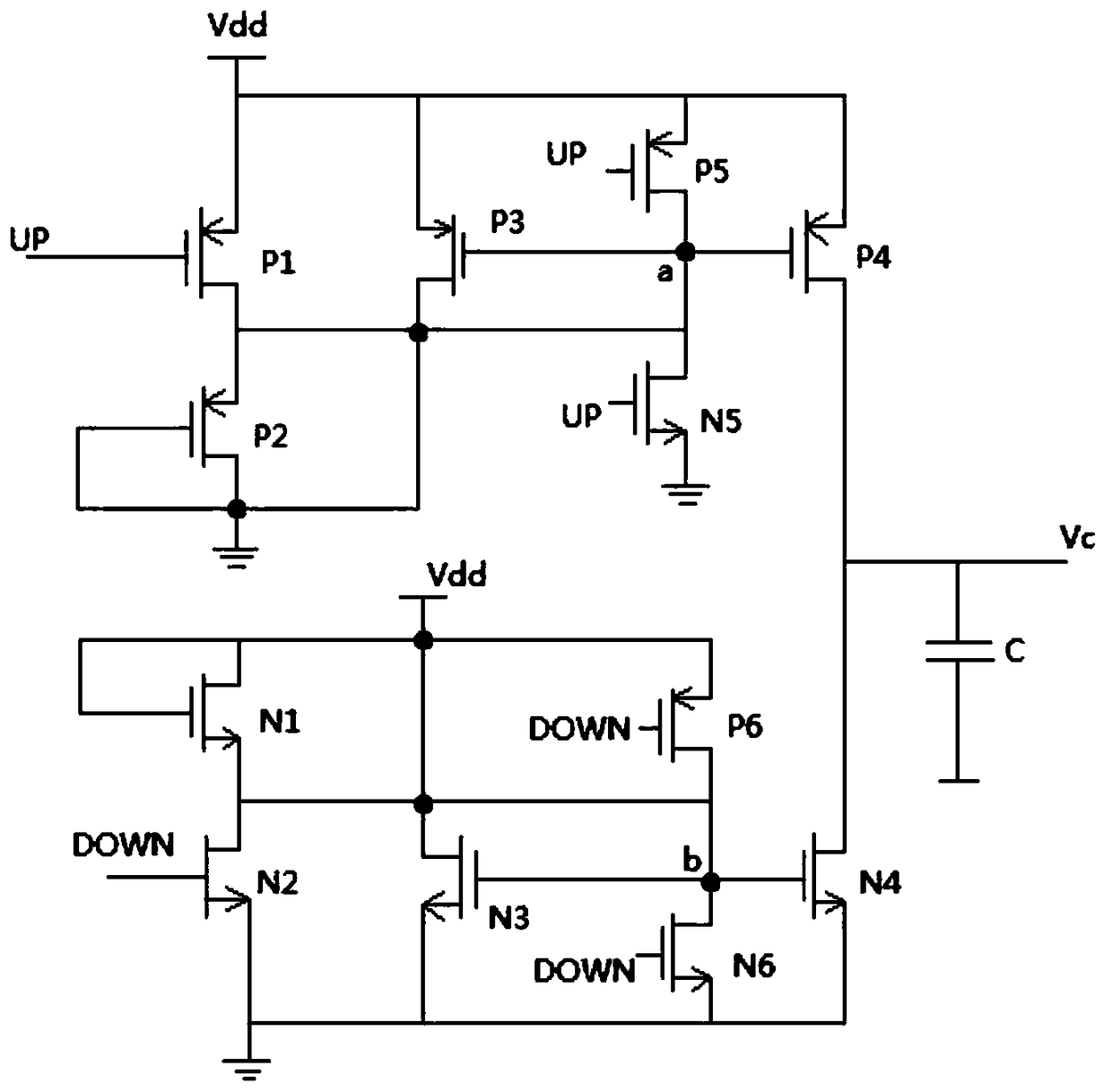
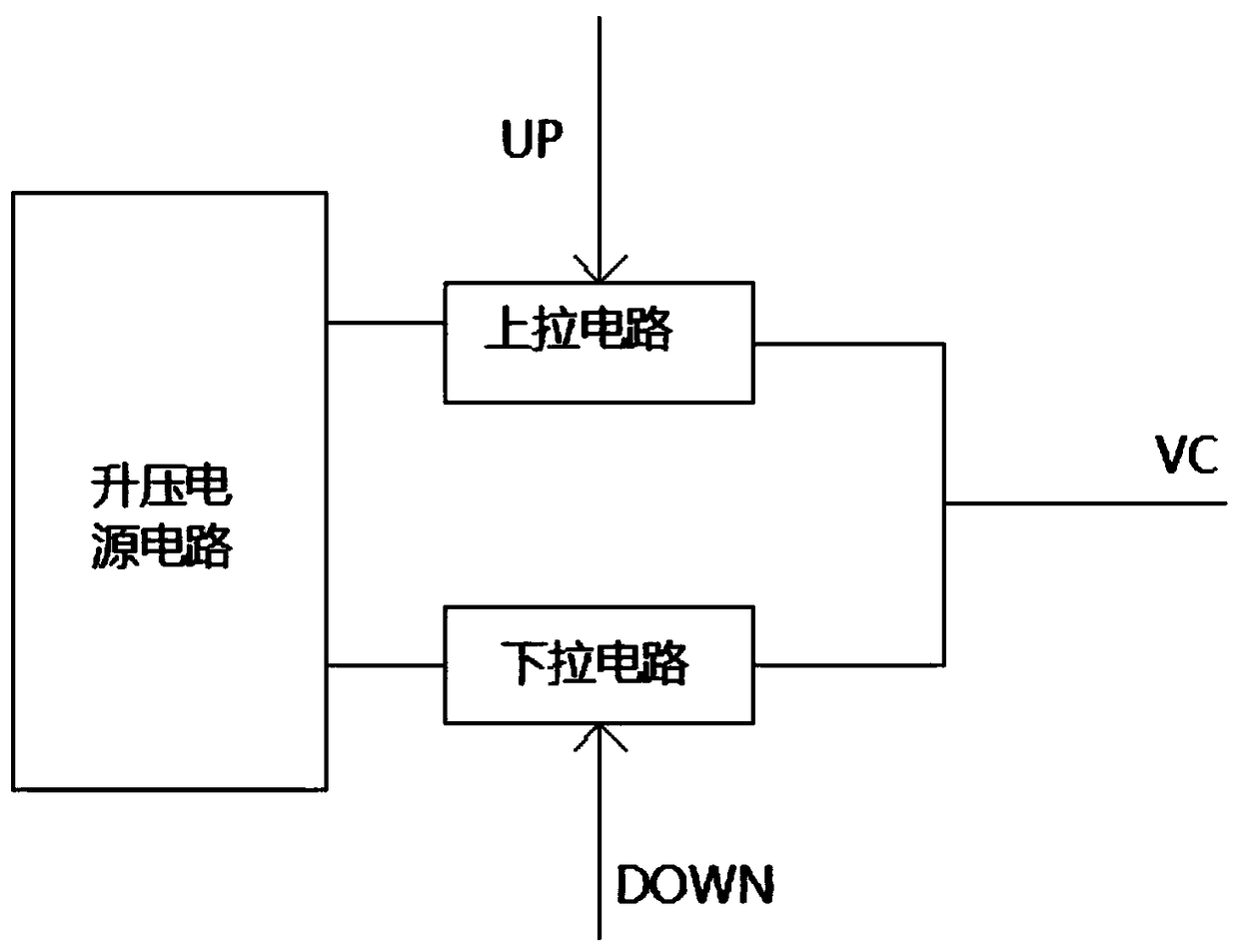
[0018] see figure 1 , in an embodiment of the present invention, a self-excited charge pump circuit includes a boost power supply circuit for providing stable power supply, a pull-up circuit for processing UP input signals, and a pull-down circuit for processing DOWN input signals, so The boost power supply circuit is connected to the pull-up circuit and the pull-down circuit respectively.

[0019] As a further solution of the present invention: the pull-up c...


PUM


Abstract

The invention discloses a self-excited charge pump circuit, which comprises a boost power supply circuit for providing stable power supply, an up-pull circuit for processing UP input signals and a pull-down circuit for processing DOWN input signals, wherein the boost power supply circuit is respectively connected with the pull-up circuit and the pull-down circuit. According to the invention, the charge pump can realize certain self-excited boost without the need of an external inductive element, due to the absence of inductive elements, the EMI problem caused by an inductor-based power sourceis overcome, and the electromagnetic interference is low, the circuit is not only high in efficiency, simple in circuit structure, small in occupation area, and low in power consumption, but also canwork efficiently under the low voltage condition of the power supply.

Description

technical field [0001] The invention relates to a charge pump circuit, in particular to a self-excited charge pump circuit. Background technique [0002] A charge pump circuit is a circuit that converts an input potential into a positive high potential or a negative low potential. Due to system requirements or the need to improve the performance of integrated circuits, there will still be high-voltage circuits or high-voltage devices inside the integrated circuit chip, so the charge pump circuit is used as the power supply circuit in the integrated circuit, that is, the charge pump circuit is used to boost the input voltage to provide a predetermined voltage circuit use. At present, the general charge pump circuit is composed of transistors, capacitors, clock drivers and so on. However, the traditional charge pump circuit needs to use a complex external clock to drive the switch transistor circuit, and the external clock circuit not only increases the complexity of the cir...

Claims


Application Information

Patent Timeline
Patent Type & Authority Applications(China)
IPC IPC(8): H02M3/07
CPCH02M3/07
Inventor 吕向东唐伟童
Owner HEFEI HENGSHUO SEMICON CO LTD
Why Eureka
Try Eureka