
A kind of optical transmission system synchronization test method

A technology of synchronous testing and optical transmission, which is applied in the field of communication, can solve the problems of remote synchronous reference reference measurement errors and limited test conditions, etc., and achieve the effects of solving measurement error problems, improving test accuracy, and reducing test costs

Active Publication Date: 2020-09-08
CHINA ACADEMY OF INFORMATION & COMM
View PDF3 Cites 0 Cited by
  • Summary
  • Abstract
  • Description
  • Claims
  • Application Information

AI Technical Summary

Problems solved by technology

[0004] This application proposes a method and system for synchronous testing of optical transmission systems to solve the problems of measurement errors of synchronous reference standards in different places and limited testing conditions.

Method used


Image

  • A kind of optical transmission system synchronization test method
  • A kind of optical transmission system synchronization test method
  • A kind of optical transmission system synchronization test method

Examples


Embodiment Construction

[0026] In order to make the purpose, technical solution and advantages of the present application clearer, the technical solution of the present application will be clearly and completely described below in conjunction with specific embodiments of the present application and corresponding drawings. Apparently, the described embodiments are only some of the embodiments of the present application, rather than all the embodiments. Based on the embodiments in this application, all other embodiments obtained by persons of ordinary skill in the art without making creative efforts belong to the scope of protection of this application.

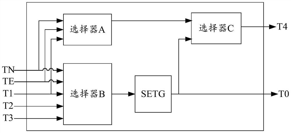
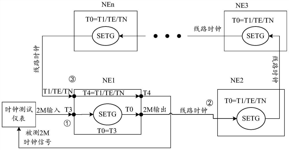
[0027] The technical key point of the present invention is to implement the clock loopback measurement through the directional derivation function T4=T1 / TE / TN of the clock selector on the optical transmission equipment. This technology is applicable to OTN / POTN, PTN or SDH / MSTP equipment in a ring network topology environment.

[0028] The present in...


PUM


Abstract

The invention discloses a synchronization testing method for light transmission system, and solves problems of different-place synchronization reference measurement errors and limited testing conditions. The method comprises the following steps: starting a clock test instrument to output a clock signal, and inputting the clock signal to an external synchronization input interface of a local network element; setting the local network element so that a signal of the external synchronization input interface is outputted as a line clock through a synchronization device timing generator output interface, and transmitting the signal to line network elements; setting each the line network element so that a signal of a line signal input interface is outputted as a line clock through the synchronization device timing generator output interface, and transmitting the tested signal to the local network element or the next line network element; setting the local network element so that the line signal input interface signal is outputted as a tested signal through the external synchronous output interface, and inputting the tested signal to the clock test instrument. The invention also proposesa corresponding testing system. The method and system improve the system test accuracy and get rid of the limitations from a test source and a test reference point.

Description

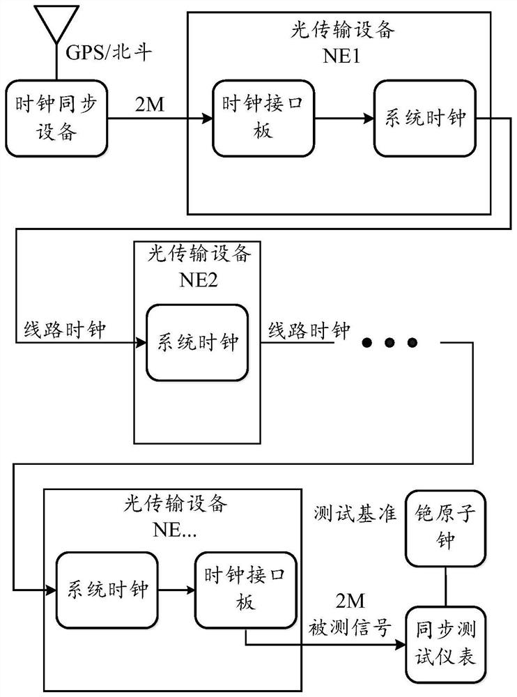
technical field [0001] The present application relates to the technical field of communication, and in particular to a method for synchronous testing of an optical transmission system. Background technique [0002] As an important support network, the synchronization network is closely connected with the transmission network. The traditional SDH / MSTP optical transmission network works in TDM mode, which requires highly reliable and high-performance clock synchronization signals to operate stably. Although OTN / PTN technology has different synchronization requirements from traditional SDH / MSTP, as an important bearer network, it needs to connect with other bearer networks for synchronization signals. Problems with frequency and time synchronization signals. [0003] SDH / MSTP, PTN, OTN optical transmission system frequency synchronization live network test plays an important role in performance verification, project commissioning, and maintenance. In different computer rooms,...

Claims


Application Information

Patent Timeline
Patent Type & Authority Patents(China)
IPC IPC(8): H04Q11/00
CPCH04B10/0793H04Q11/0062H04Q2011/0083
Inventor 吕博胡昌军潘峰
Owner CHINA ACADEMY OF INFORMATION & COMM
Learn More