Cylinder head camshaft hole machining machine tool and using method thereof

A camshaft hole and machine tool technology, which is applied to metal processing machinery parts, metal processing equipment, tool holders, etc., can solve the problems of low processing efficiency of cylinder head camshaft holes, achieve high cutting processing efficiency, and improve processing progress Effect

Pending Publication Date: 2018-10-19
河南太行精铸制造有限公司
View PDF2 Cites 2 Cited by
  • Summary
  • Abstract
  • Description
  • Claims
  • Application Information

AI Technical Summary

Problems solved by technology

[0006] In view of this, the purpose of the present invention is to address the deficiencies in the prior art, to provide a cylinder head camshaft hole processing machine tool and its use method, and to solve the problems of the engine cylinder head camshaft in the prior art by using a cutter with a plurality of cutter heads. The problem of low hole processing efficiency, and the use of multi-point support improves the stability of the tool and increases the machining accuracy, and the accurate positioning of the sensor makes it difficult to cause damage to the tool or workpiece due to human error during the process.

Method used


Image

  • Cylinder head camshaft hole machining machine tool and using method thereof
  • Cylinder head camshaft hole machining machine tool and using method thereof
  • Cylinder head camshaft hole machining machine tool and using method thereof

Examples


Embodiment Construction

[0038] The present invention will be further described below in conjunction with the accompanying drawings and embodiments.

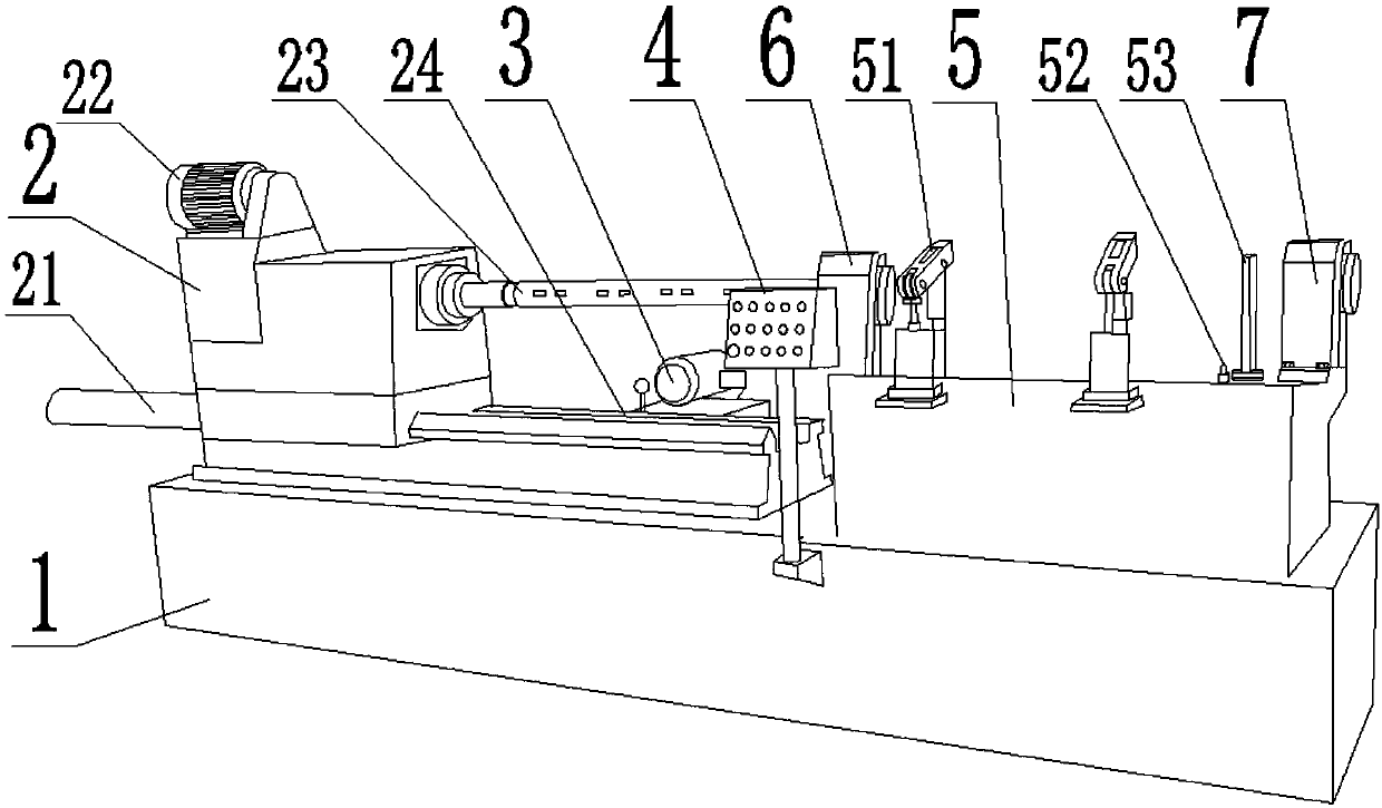
[0039] Such as figure 1 As shown, a cylinder head camshaft hole processing machine tool includes a frame 1, and the frame 1 is provided with a tool rest 2, a clamp 5, a console 4 and a hydraulic station 3;

[0040] The knife rest 2 moves linearly on the track 24 provided on the frame 1 through the knife rest telescopic cylinder 21, and the knife rest 2 is also provided with a rod-shaped cutter 23 parallel to the track 24 and a driving device for rotating the cutter 23 22. The driving device 22 includes a motor and a gearbox, and the gearbox is a multi-speed gearbox, which can provide different rotation speeds for the cutter 23 during rough bore or fine bore, so as to ensure the safety of the cutter 23 and the accuracy of machining promote.

[0041] Described cutter 23 comprises cutter bar, and described cutter bar is cylindrical, and described cutter ...


PUM


Abstract

The invention discloses a cylinder head camshaft hole machining machine tool. The cylinder head camshaft hole machining machine tool comprises a frame. A cutter rest, a clamp, a console and a hydraulic station are arranged on the frame. A rod-shaped cutter, a driving device for rotating the cutter and support frames arranged in the advancing direction of the cutter are arranged on the cutter rest.The cutter comprises a cutter bar. Multiple sets of grooves are formed in the cutter bar. The two grooves, namely the fine boring cutter and the rough boring cutter, are formed in each set. The fineboring cutters or the rough boring cutters are fixed in the grooves by fasteners. Clamps are arranged between the support frames, and multiple support blocks, limiting blocks, retractable positioningpins and clamping arms are arranged on each clamp. The invention further discloses a using method of the cylinder head camshaft hole machining machine tool. The cylinder head camshaft hole machining machine tool and the using method solve the problem that the machining efficiency of an engine cylinder head camshaft hole in the prior art is low, and the accurate positioning by sensors makes it difficult for the cutter or a workpiece to be damaged due to human operation error during the machining process.

Description

technical field [0001] The invention relates to the field of automobile manufacturing, in particular to a machine tool for processing cylinder head camshaft holes and a method for using the same. Background technique [0002] At present, China's automobile manufacturing technology is developing in the direction of high speed, intelligence, compounding, and environmental protection. Among them, engine manufacturing technology is the representative. As an important part of the engine, the holes for connecting rods, crankshafts and piston pins require high precision. Rough boring, fine boring, reaming and polishing processes are mostly used, among which the accuracy and difficulty of reaming are the highest. This puts forward high requirements for cutting tools. How to provide high-quality products for automobile and parts manufacturers, and reduce costs and increase efficiency to the greatest extent, while providing a complete overall solution for cutting processing, has becom...

Claims


Application Information

Patent Timeline
Patent Type & Authority Applications(China)
IPC IPC(8): B23B29/24B23Q17/22B23B35/00
CPCB23B29/244B23B35/00B23Q17/2208
Inventor 马育刚张玉茹杨国喜张玉新
Owner 河南太行精铸制造有限公司
Why Eureka
Try Eureka