Electric tool based on micro motor
A technology of electric tools and micro-special motors, which is applied in the manufacture of tools, portable motorized devices, circuits, etc. It can solve the problems of insufficient rotation force of the shift wire, affect the service life of electric tools, and cannot accurately shift gears, etc., to achieve flexibility Good reset effect, improved elasticity, and increased overall length
- Summary
- Abstract
- Description
- Claims
- Application Information
AI Technical Summary
Problems solved by technology
Method used
Image
Examples
Embodiment 1
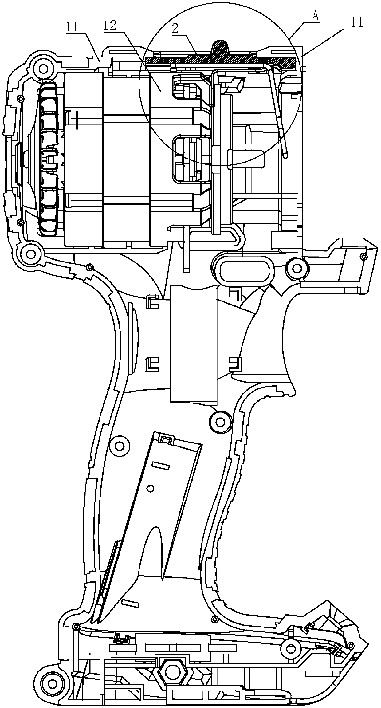
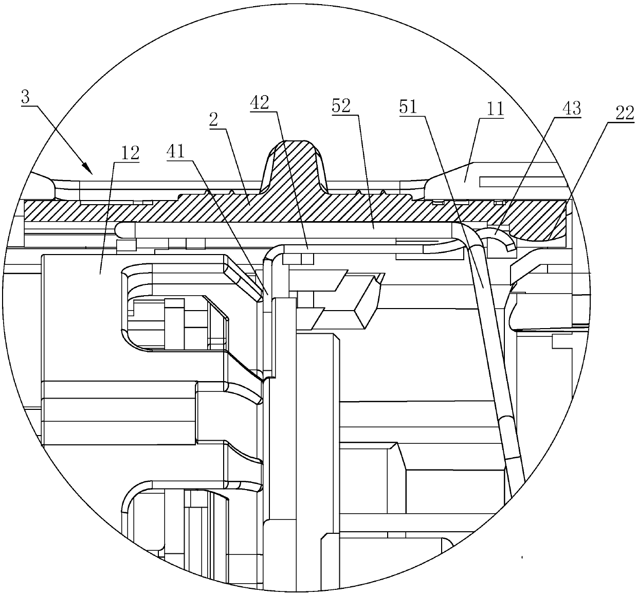
[0013] Embodiment 1: An electric tool based on a micro motor, including a housing 11, a motor 12, a shift push button 2 and a shift wire, the motor 12 is arranged in the housing 11, and the housing 11 is provided with a push groove 3 , the shift push button 2 is located in the push groove 3 and can move back and forth in the push groove 3, the shift steel wire is arranged at the bottom of the shift push button 2, the upper end of the shift steel wire is fixedly connected with the shift push button 2, and the motor 12 An elastic positioning piece is arranged on the top, and the elastic positioning piece includes a fixed piece 41 and an elastic piece 42. The fixed piece 41 is fixedly connected with the motor 12, and the elastic piece 42 is bent and connected to the upper end of the fixed piece 41 in a cantilever structure. Below the push button 2, an upwardly protruding arc-shaped bump 43 is provided on the elastic piece 42. The arc-shaped bump 43 is used to connect the front par...
Embodiment 2
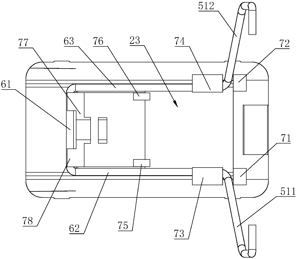
[0014] Embodiment 2: The remaining parts are the same as Embodiment 1, the difference is that the shift wire includes a shift portion 51 and a positioning portion 52 integrally arranged, the lower surface of the shift push button 2 is provided with a positioning cavity 23, and the positioning portion 52 is fixedly arranged in the positioning cavity 23, and a positioning mechanism for fixing the positioning part 52 is provided on the lower surface of the shift push button 2, and the shift part 51 is used for shifting according to the pushing action of the shift push button 2 Switching, the shift part 51 includes a left shift lever 511 and a right shift lever 512 symmetrically arranged on both sides of the housing 11, and the positioning part 52 includes a positioning rod 61 and a left connecting rod 62 and a right connecting rod 63 arranged symmetrically. Positioning mechanism comprises left top block 71, right top block 72, left briquetting block 73, right briquetting block 74,...
Embodiment 3
[0015] Embodiment 3: the rest is the same as Embodiment 2, the difference is that the rear stopper 77 is provided with a rear pressing block 78 , and the positioning rod 61 is located between the rear pressing block 78 and the bottom of the positioning cavity 23 .
PUM
 Abstract
Description
Claims
Application Information
 - R&D
- Intellectual Property
- Life Sciences
- Materials
- Tech Scout
- Unparalleled Data Quality
- Higher Quality Content
- 60% Fewer Hallucinations
Browse by: Latest US Patents, China's latest patents, Technical Efficacy Thesaurus, Application Domain, Technology Topic, Popular Technical Reports.
© 2025 PatSnap. All rights reserved.Legal|Privacy policy|Modern Slavery Act Transparency Statement|Sitemap|About US| Contact US: help@patsnap.com


