Elevated station

A technology for stations and viaducts, which is applied to bridge parts, safety islands, public buildings, etc. It can solve the problems of large substructure size, large volume, self-heaviness of cast-in-place concrete structures, etc., and achieve the effect of reducing noise

Pending Publication Date: 2018-10-19
CHINA RAILWAY SIYUAN GRP SOUTHWEST SURVEY & DESIGN CO LTD +1
View PDF10 Cites 5 Cited by
  • Summary
  • Abstract
  • Description
  • Claims
  • Application Information

AI Technical Summary

Problems solved by technology

[0003] Most of the current tram elevated stations refer to the design of urban rail transit elevated stations. The structures of track beams, platform beams, escalators, pedestrian bridges, and canopy columns are all complete and each component can independently undertake corresponding functions. Some tram elevated stations have complex structures and large volumes, and the design should be optimized. The standardization, assembly, and lightweight of the station structure are also problems to be sol...

Method used


Image

  • Elevated station
  • Elevated station
  • Elevated station

Examples


Embodiment 1

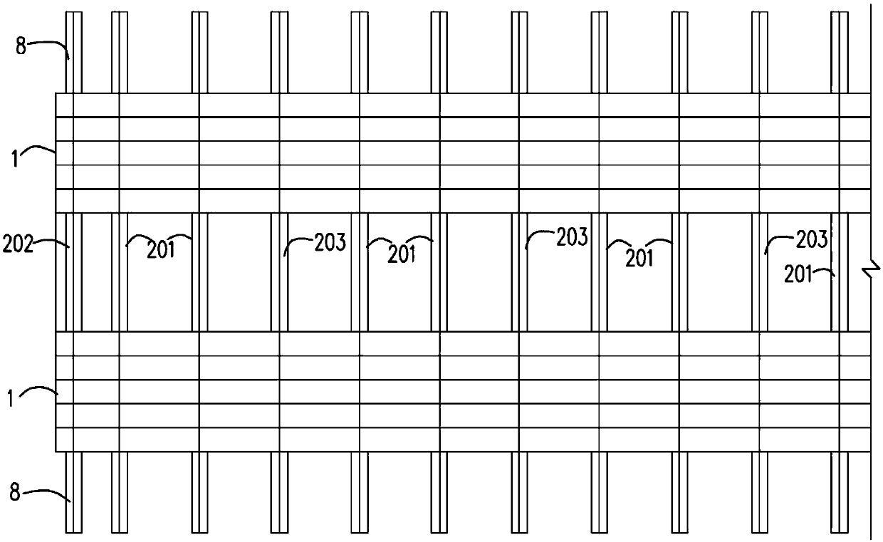
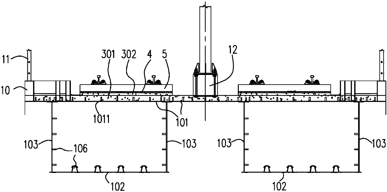
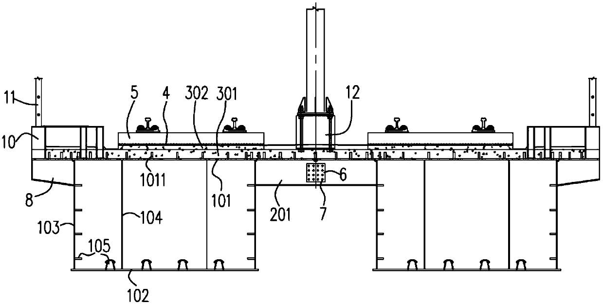
[0034] like Figure 1-Figure 6 , the embodiment of the present invention provides an elevated steel-concrete composite beam, including at least two separated steel boxes 1, each of which includes a box top plate 101, a box bottom plate 102 and two webs 103, the The box roof 101, the box bottom 102 and the two webs 103 are connected to form a box structure, and each of the box roofs 101 is poured with a concrete layer; each of the separated steel boxes 1 is arranged in sequence along the beam transverse direction, each Two adjacent separated steel boxes 1 are spliced ​​by a cross-connection mechanism. The cross-connection mechanism includes a plurality of cross-connection groups arranged in sequence along the longitudinal direction of the beam. 6 and bolts 7 are sequentially spliced ​​with a plurality of cross-connecting plates, and each of the cross-connecting plates is respectively connected to the box roof 101 of the corresponding separated steel box 1. Wherein, it is easy ...

Embodiment 2

[0057] like Figure 7-Figure 10An embodiment of the present invention provides an elevated station, including a superstructure and a substructure 2000, the substructure 2000 supports the superstructure, wherein the superstructure includes a viaduct 1000, a platform slab 5000 arranged on the viaduct 1000 and For the canopy 6000, the elevated beam 1000 is preferably the elevated steel-concrete composite beam provided in the first embodiment above, and the structure of the elevated steel-concrete composite beam will not be repeated here.

[0058] like Figure 8-Figure 10 , preferably, the elevated girder 1000 adopts a cross-connection group structure including three cross-connection plates and the two joints are respectively close to the corresponding two separate steel boxes 1, so that the station structure is stable and reliable.

[0059] like Figure 8 and Figure 9 , preferably, the elevated beam 1000 adopts a structure in which the two lateral sides of the beam are provid...


PUM


Abstract

The invention relates to an elevated station. The elevated station comprises an upper structure and a lower structure, wherein the upper structure comprises an elevated steel-concrete composite beam,a platform board arranged on the elevated beam and a rain shed, wherein the elevated beam comprises at least two separation type steel boxes, and a concrete layer is poured on a top plate of each box;the separation type steel boxes are sequentially arranged in the horizontal direction of the beam, every two adjacent separation type steel boxes are connected through a lateral combination mechanism, each lateral combination mechanism comprises multiple lateral combination groups arranged sequentially in the longitudinal direction of the beam, and each lateral combination group comprises multiple lateral combination plates which are sequentially spliced through splicing plates and bolts in the horizontal direction of the beam and are connected with top plates of the corresponding separationtype steel boxes. The elevated station adopts the elevated steel-concrete composite beam and the separation type steel boxes, the separation type steel boxes are spliced into a whole beam through lateral combination mechanisms, standard design, factory production and prefabricated construction can be realized, and the concrete top plates of the steel-concrete composite beam can have a function ofreducing noise of a steel bridge.

Description

technical field [0001] The invention relates to an elevated station. Background technique [0002] Modern tram is a low-capacity urban rail transit, which is between light rail and bus. It has the characteristics of low noise, low vibration, energy saving, comfort and convenience, environmental protection and beauty. There are many cities that have built or are building modern trams, and there is a trend of accelerated development. Tram tracks are mainly laid on urban roads and run mixed with other ground transportation. A small number of trams are elevated stations. Elevated stations should be simple, short construction period, little interference to urban traffic, low life cycle cost, and green and environmentally friendly. At present, most tram elevated stations adopt large-scale cast-in-place concrete structures. The cast-in-place concrete structure has problems such as long construction period, heavy structure, many construction measures, great interference to existin...

Claims


Application Information

Patent Timeline
IPC IPC(8): E04H3/00E01F1/00E01D2/04E01D19/02
CPCE01D2/04E01D19/02E01F1/00E04H3/00
Inventor 黎泰良贾伦学裴利华徐永浩陈焰焰
Owner CHINA RAILWAY SIYUAN GRP SOUTHWEST SURVEY & DESIGN CO LTD
Why Eureka
Try Eureka