
Efficient contra-rotating axial flow pump

An axial flow pump, high-efficiency technology, applied in the field of axial flow pump research, can solve problems such as flow analysis without front and rear impeller coupling, single load distribution coefficient, etc.

Active Publication Date: 2018-10-19
JIANGSU UNIV
View PDF6 Cites 8 Cited by
  • Summary
  • Abstract
  • Description
  • Claims
  • Application Information

AI Technical Summary

Problems solved by technology

[0004] Since 2002, Wang Dejun of Tsinghua University in China has started a series of research on counter-rotating axial flow pumps, established the basic theory and basic methods of model design, and proposed the "upward-warped" blade design and joint optimization method, but since then there have been few Regarding the relevant research and patent reports on counter-rotating axial flow pumps, Wang Kai of Huazhong University of Science and Technology conducted model design and related numerical analysis research on reversible counter-rotating axial flow pumps in 2014, but they were limited to a single load distribution coefficient. The study did not carry out further analysis on the speed distribution and the coupling flow of the front and rear impellers. On the basis of the predecessors, the present invention has made a detailed definition and research on the speed and load distribution, and further improved the coupling flow characteristics of the front and rear impellers. Modeling and analysis of the front and rear impeller series of counter-rotating axial flow pumps, and simulation by ANSYS CFX, a high-efficiency counter-rotating axial flow pump impeller structure and hydraulic design technology are proposed, which can be used as design reference

Method used


Image

  • Efficient contra-rotating axial flow pump
  • Efficient contra-rotating axial flow pump
  • Efficient contra-rotating axial flow pump

Examples


Embodiment Construction

[0070] The present invention will be further described below in conjunction with the accompanying drawings and specific embodiments.

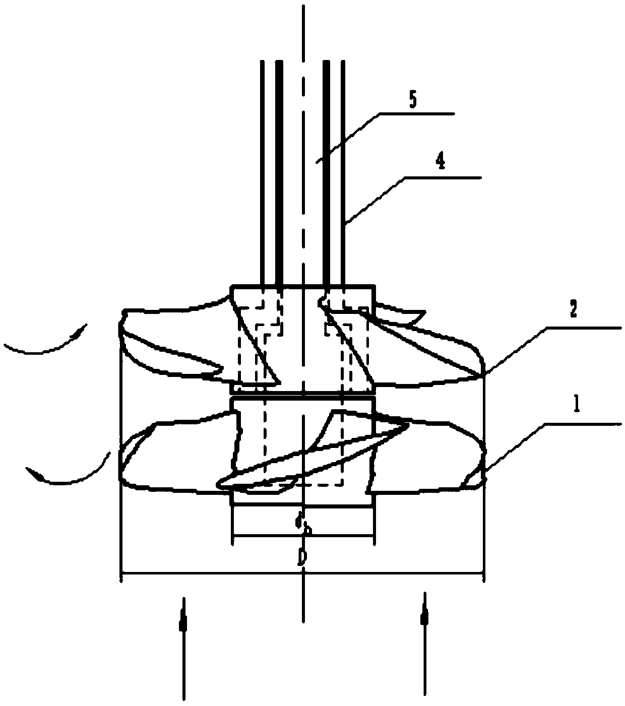
[0071] Such as image 3 As shown, the high-efficiency counter-rotating axial flow pump of the present invention includes a front impeller 1 , a rear impeller 2 , a dual-rotor counter-rotating permanent magnet motor 3 , an outer rotor shaft 4 and an inner rotor shaft 5 .

[0072] The front impeller 1 is driven to rotate by the outer rotor shaft 4 and fixed by the key between the outer rotor shaft 4 and the front impeller 1, and the rear impeller 2 is driven to rotate by the inner rotor shaft 5 and connected to the rear by the inner rotor shaft 5. The keys between the impellers 2 are fixed, and the inner rotor shaft 5 and the outer rotor shaft 4 are fixed in the dual-rotor counter-rotating permanent magnet motor 3 and driven to rotate by the dual-rotor counter-rotating permanent magnet motor 3 . The liquid flows in from the front impeller 1 axia...


PUM


Abstract

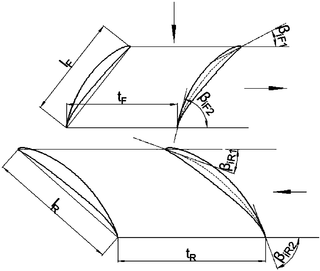
The invention provides an efficient contra-rotating axial flow pump. The efficient contra-rotating axial flow pump comprises a front impeller, a rear impeller and a double-rotor contra-rotating motor,wherein the front impeller is connected to an outer rotor shaft of the double-rotor contra-rotating motor, and the rear impeller is connected to an inner rotor shaft of the double-rotor contra-rotating motor; and the front impeller and the rear impeller are opposite in rotation directions, and the front impeller and the rear impeller have the same wheel edge diameter D and hub diameter dh. According to the efficient contra-rotating axial flow pump, the efficient contra-rotating axial flow pump is reasonably optimally designed on the basis of an original axial flow pump impeller design methodand according to the structure properties and the flowing condition of the contra-rotating axial flow pump, and particularly wing shaped mounting corners at the coupling flowing positions at the frontimpeller and the rear impeller of the contra-rotating axial flow pump are subjected to reasonable flowing setting, so that the hydraulic efficiency of the contra-rotating axial flow pump is improved.

Description

technical field [0001] The invention belongs to the research field of axial-flow pumps, and is particularly aimed at a high-efficiency counter-rotating axial-flow pump. Background technique [0002] Axial flow pump is a kind of vane pump, which uses the force generated by the blades of the rotating impeller on the liquid to transport the liquid along the axial direction. Axial flow pump is the one with the highest specific speed among dynamic pumps. It is mainly suitable for super large flow occasions, such as irrigation, drainage, dock drainage, water level adjustment of canal locks, or as a large circulating water pump in power plants. [0003] Compared with the traditional single-stage axial flow pump, the counter-rotating axial flow pump is an axial flow pump obtained by replacing the rear stationary vane of the traditional axial flow pump with the rear movable vane, and the front and rear impellers rotate in reverse. The rear impeller can not only recover the kinetic e...

Claims


Application Information

Patent Timeline
Patent Type & Authority Applications(China)
IPC IPC(8): F04D3/00F04D13/06F04D29/18G06F17/50
CPCF04D3/00F04D13/06F04D29/185G06F30/17
Inventor 王秀礼方杰朱荣生付强
Owner JIANGSU UNIV
Learn More