High-resolution, large-image-plane, small-size and infrared confocal zoom optical system

A high-resolution, infrared confocal technology, applied in the field of zoom optical system, can solve the problems of difficult control, lens volume change, monitoring distance change, etc., to achieve the effect of adjusting definition, high photosensitive performance and improving effect

Active Publication Date: 2018-10-19
UNION OPTECH
View PDF5 Cites 3 Cited by
  • Summary
  • Abstract
  • Description
  • Claims
  • Application Information

AI Technical Summary

Problems solved by technology

[0003] Ordinary zoom lenses are often not compatible with large image area and volume. The increase of image area will cause a sharp change in lens volume. Currently, large-screen surveillance lenses on the market, such as lenses with a size of about 1″, have an image area of ​​16.0 mm, its volume is relatively large, and most of them are fixed-focus lenses, which are difficult to control when the monitoring distance changes;
[0004] At present, the mainstream high-quality surveillance cameras on the market have a low resolution, mostly 1080p, with 2 million pixels. However, with the improvement of data transmission speed, higher-quality image transmission becomes possible. It cannot meet the demand; the current mainstream 1080P lens image plane is mainly 1 / 2.8″, using a 1 / 2.8″ CMOS chip with an effective imaging plane diagonal of 6.2mm, its pixel size is only 2.8μm, and the resolution Not very high; and because the pixels are small, its photosensitivity and color reproduction are not very ideal, and performance improvement is urgently needed;
[0005] Most of the surveillance lenses currently on the market are non-infrared confocal lenses. Therefore, in occasions with many optical wavelength bands, such as in the evening, or when there is some lighting at night, the captured picture cannot be clear as a whole, and there will always be some blurring;

Method used


Image

  • High-resolution, large-image-plane, small-size and infrared confocal zoom optical system
  • High-resolution, large-image-plane, small-size and infrared confocal zoom optical system
  • High-resolution, large-image-plane, small-size and infrared confocal zoom optical system

Examples


Embodiment Construction

[0028] The following combination figure 1 For further clarification:

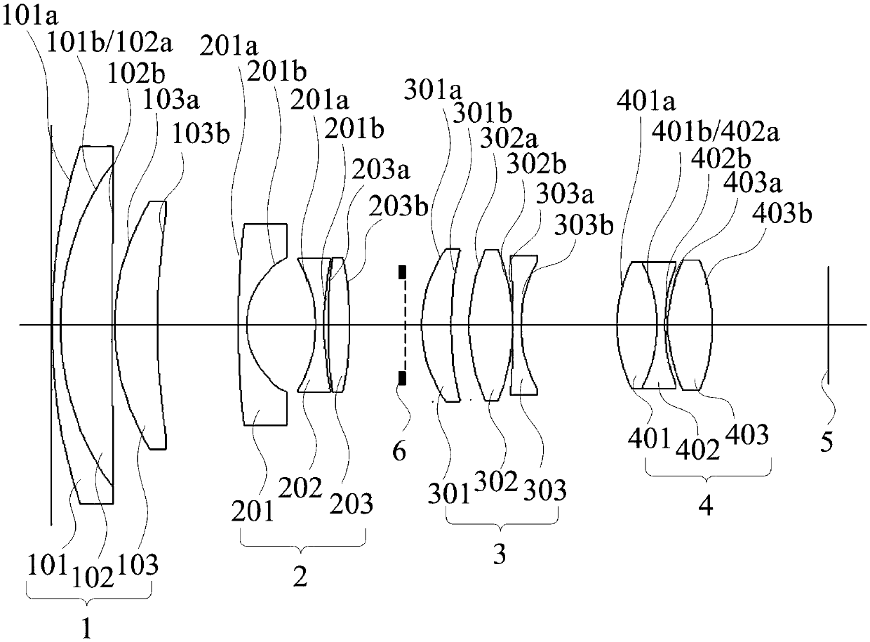
[0029] A high-resolution, large image area, small volume, infrared confocal zoom optical system, which is sequentially equipped from the object side to the image side:

[0030] A first lens group 1 with a positive focal length, a second lens group 2 with a negative focal length, an iris 6, a third lens group 3 with a positive focal length, a fourth lens group 4 with a positive focal length, and a photosensitive chip 5;

[0031] The first lens group 1, the iris 6 and the third lens group 3 are fixed relative to the photosensitive chip 5, the second lens group 2 and the fourth lens group 4 can move back and forth relative to the photosensitive chip 5, and the optical system is from a short focal length to a long focal length During the change process, the second lens group 2 gradually moves to the third lens group 3, and the fourth lens group 4 moves relative to the photosensitive chip 5 to achieve the effec...


PUM


Abstract

The invention relates to the technical field of an optical lens, in particular to a high-resolution, large-image-plane, small-size and infrared confocal zoom optical system, which is sequentially provided with, from an object side to an image side, a first lens group with a positive focal length, a second lens group with a negative focal length, a diaphragm, a third lens group with a positive focal length, a fourth lens group with a positive focal length and a photosensitive chip. The first lens group, the diaphragm and the third lens group are fixed with respect to the photosensitive chip, the second lens group and the fourth lens group can move forward and backward with respect to the photosensitive chip, the second lens group moves toward the third lens group gradually when the opticalsystem changes from a short focal length to a long focal length, and a focusing effect is realized when the fourth lens group moves with respect to the photosensitive chip. The third lens group includes three lenses, wherein one aspheric lens in the third lens group and one aspheric lens arranged in the second lens group can perform aberration correction. An aspheric lens in the fourth lens groupcan perform correction of the field curvature.

Description

technical field [0001] The invention relates to the technical field of optical lenses, in particular to a zoom optical system with high resolution, large image plane, small volume and infrared confocal. Background technique [0002] At present, zoom lenses are widely used in people's daily life. The current market is developing in the direction of high resolution and high image quality. In order to obtain better imaging quality, using chips with larger pixels and more pixels is the solution to the problem. One of the fundamental ways, but the current security monitoring and road condition monitoring devices have the following shortcomings: [0003] Ordinary zoom lenses are often not compatible with large image area and volume. The increase of image area will cause a sharp change in lens volume. Currently, large-screen surveillance lenses on the market, such as lenses with a size of about 1″, have an image area of ​​16.0 mm, its volume is relatively large, and most of them a...

Claims


Application Information

Patent Timeline
Patent Type & Authority Applications(China)
IPC IPC(8): G02B15/173
CPCG02B15/173
Inventor 王东阳龚俊强欧俊星王晓李建华
Owner UNION OPTECH
Why Eureka
Try Eureka