Plasma electric field generator

An electric field generator, plasma technology, applied in solid separation, electrode structure, electrostatic separation, etc., can solve problems such as safety hazards, cathode rod jitter, power short circuit, etc., to avoid short circuit, reduce wind speed, and good stability.

Pending Publication Date: 2018-10-23
广东本立环保技术有限公司
View PDF0 Cites 4 Cited by
  • Summary
  • Abstract
  • Description
  • Claims
  • Application Information

AI Technical Summary

Problems solved by technology

[0004] In the traditional plasma electric field generator, all the cathode rods are fixed at one end, which will cause the cathode rod to vibrate due to the large air volume and wind pressure when the exhaust gas passes through the anode tube, and will touch the anode tube, short-circuiting the power supply and causing safety hazards

Method used


Image

  • Plasma electric field generator
  • Plasma electric field generator
  • Plasma electric field generator

Examples


Embodiment Construction

[0028] The present invention will be described below in conjunction with the accompanying drawings and specific embodiments.

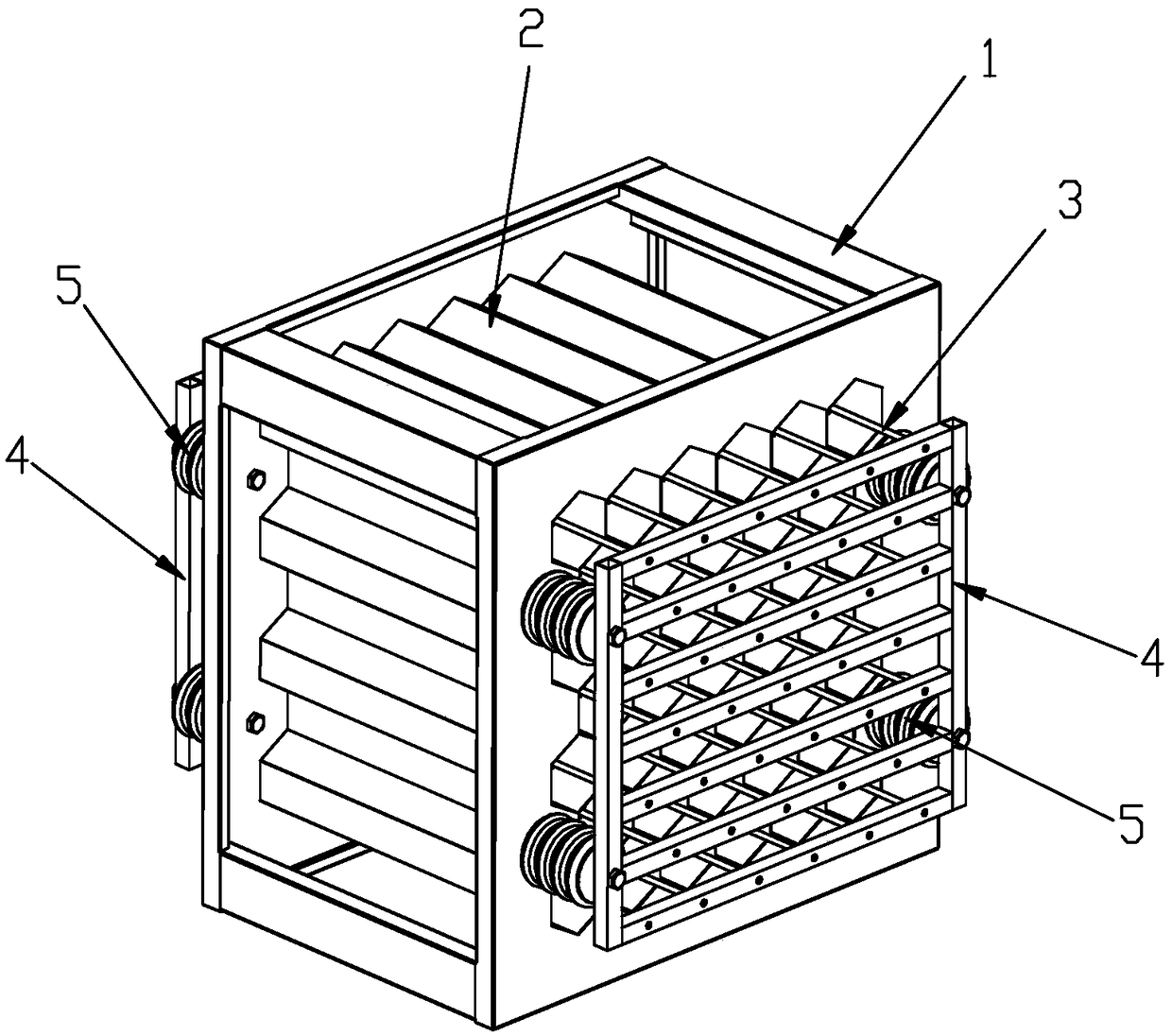
[0029] refer to Figure 2-6 :

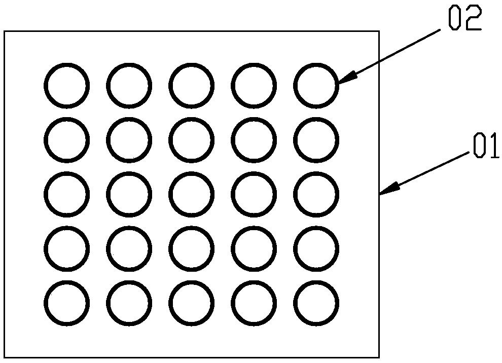
[0030] A plasma electric field generator, comprising an anode tube group 2 installed on a main frame 1, a cathode rod group 3 arranged in the anode tube group 2 in one-to-one correspondence, and a device for fixing the cathode rod group 3 on the main frame 1 Subframe 4.

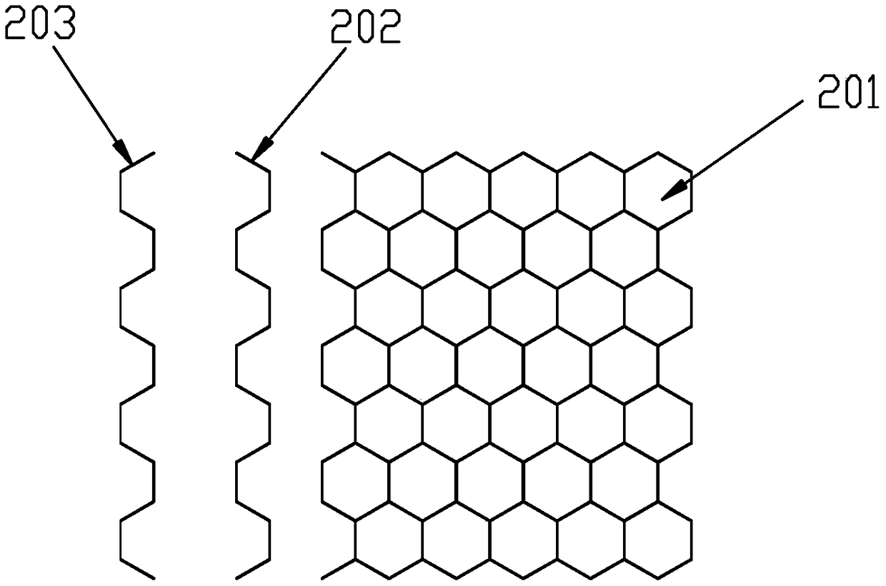
[0031] The anode tube group 2 is provided with a plurality of regular hexagonal lumens 201 arranged in a matrix, and all adjacent lumens 201 share a tube wall to form a honeycomb tube group composed of continuous regular hexagonal tube groups .

[0032] The anode tube group 2 is formed by alternate splicing of a plurality of first pattern plates 202 and a plurality of second pattern plates 203 .

[0033] Both sides of the first template 202 and the second template 203 are alternately provided with a plurality of isosceles trapezoidal notches 204 tha...


PUM


Abstract

The invention relates to a plasma electric field generator. The plasma electric field generator comprises an anode tube group, cathode bar groups and a sub-frame, wherein the anode tube group is mounted on a main frame; the cathode bar groups are arranged in the anode tube group in a one-to-one correspondence manner; the sub-frame is used for fixing the cathode bar groups on the main frame; the anode tube group is provided with a plurality of regular hexagonal tube cavities arranged like a matrix; all the adjacent tube cavities share tube walls so as to form a cellular tube group formed by continuous regular hexagonal tube groups. The plasma electric field generator is high in structural strength, good in stability, large in air cross area, wide in corona range and high in safety.

Description

technical field [0001] The invention relates to a structural improvement of a plasma electric field generator. Background technique [0002] Such as figure 1 As shown, the anode tube group of the traditional plasma electric field generator includes a tube base 01, and a plurality of circular holes are arranged in an array on the tube base 01, and a circular anode tube 02 is inserted into each circular tube hole. To form a honeycomb tube group. Since each anode tube has to independently bear the weight from the tube base above it, the tube wall is easily deformed, which changes the cross-sectional area of ​​the wind; because the hole walls between adjacent circular holes cannot overlap, no holes are set on the tube base The blank area is relatively large, resulting in the anode tube group with the same cross-sectional area, the cross-sectional area of ​​the wind is small, which is not conducive to reducing the wind speed and improving the electrolysis effect. [0003] In t...

Claims


Application Information

Patent Timeline
Patent Type & Authority Applications(China)
IPC IPC(8): B03C3/49B03C3/41
CPCB03C3/49B03C3/41B03C2201/08
Inventor 邓舜天
Owner 广东本立环保技术有限公司
Why Eureka
Try Eureka