A compact pneumatic tooling

A pneumatic tooling, compact technology, applied in the direction of manufacturing tools, positioning devices, metal processing equipment, etc., can solve the problems of high cost, actual position error of parts, pain for debugging personnel, etc., to expand the scope of application, avoid leakage clamping, The effect of improving reliability

Active Publication Date: 2019-08-06
CHANGZHOU INST OF MECHATRONIC TECH
View PDF5 Cites 0 Cited by
  • Summary
  • Abstract
  • Description
  • Claims
  • Application Information

AI Technical Summary

Problems solved by technology

[0003] Most of the fixtures used on CNC milling machines or machining centers are general-purpose fixtures, which cannot meet the actual use requirements of large quantities or high precision, and the disassembly of workpieces takes a high proportion of working time
Some factories install multiple general-purpose fixtures within the limited stroke of the machine tool. This method solves the time ratio of disassembling the workpiece to a certain extent, but this method cannot solve the weakness in the tooling debugging stage. Basically, the entire debugging time It is repetitive work, and the interchangeability of universal fixtures and universal fixtures cannot be guaranteed, and the automatic clamping of tooling cannot be realized, and the automatic loosening of tooling cannot be realized. The debugging personnel are in great pain.
Some CNC machine tools use the way of exchanging worktables to realize the disassembly and assembly of workpieces outside the machine. Generally speaking, the cost is huge, and there are inevitable errors in the actual position of the parts after the exchange.

Method used


Image

  • A compact pneumatic tooling
  • A compact pneumatic tooling
  • A compact pneumatic tooling

Examples


Embodiment 1

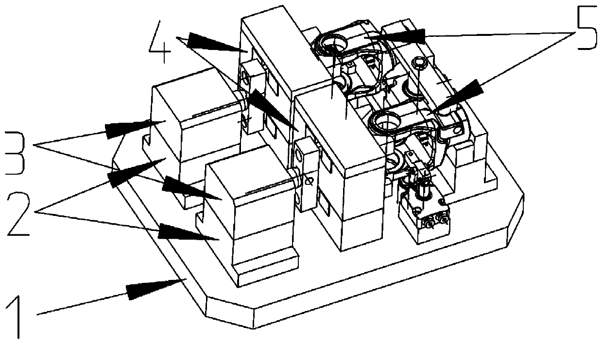
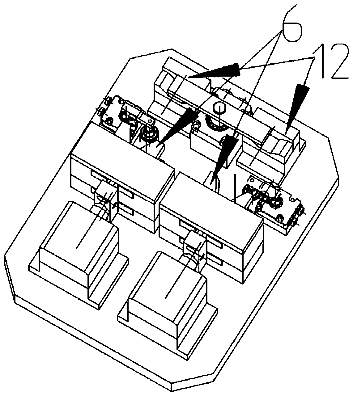
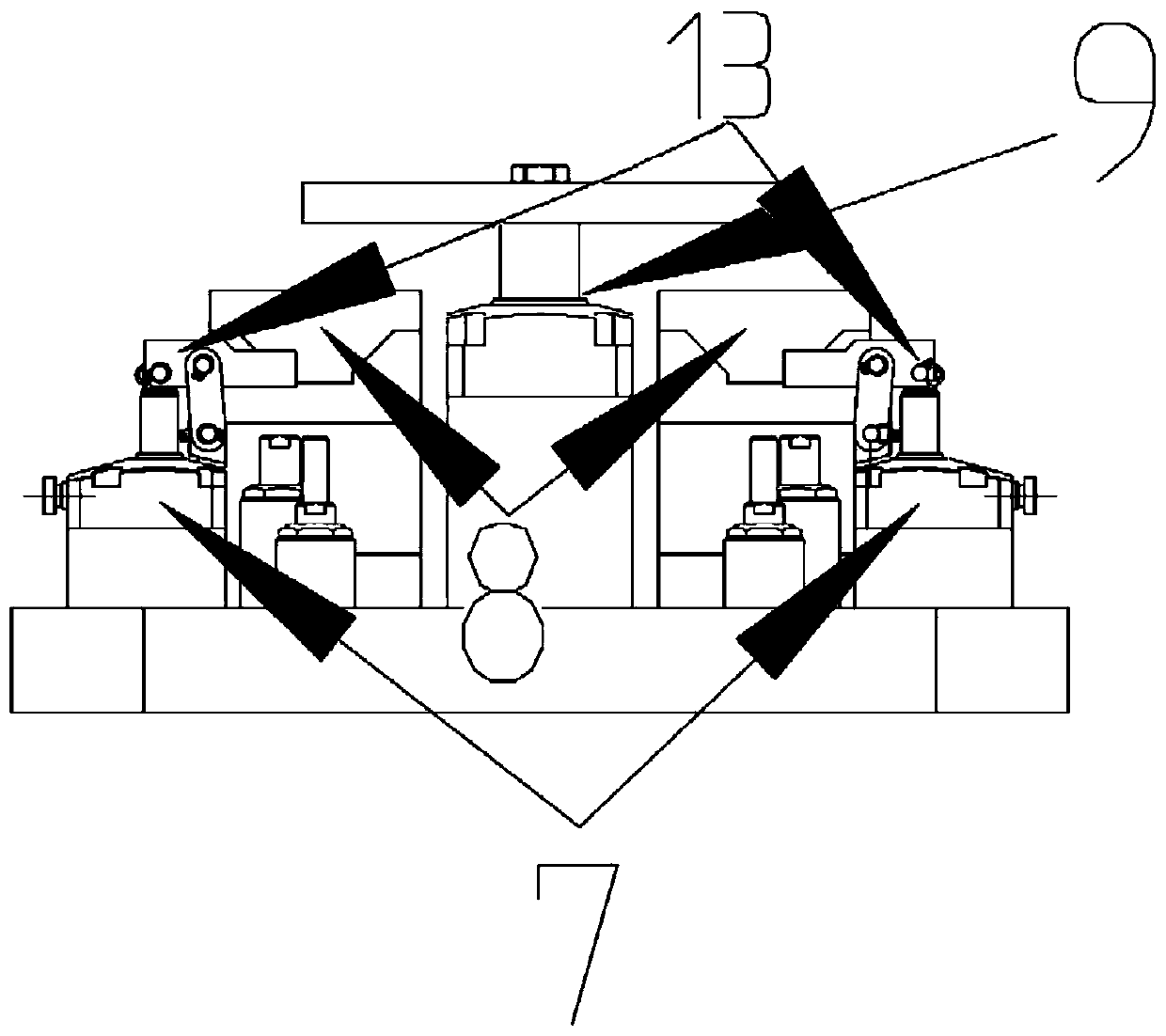
[0026] Such as figure 1 As shown, a compact pneumatic tooling of the present invention includes a fixed base plate (1), two push cylinder fixing seats (2), two main push cylinders (3), two clamp holders (4), two artifact(5); eg figure 2 Shown two fixture clamping parts (6); As shown in Figure (3) two press-down auxiliary cylinders (7), two workpiece positioning blocks (8), a main press-down cylinder (9); Figure 4 The front support block (10) and the rear support block (11) are shown, the push cylinder fixed seat is fixed on the fixed base plate, the main push cylinder is fixed on the push cylinder fixed seat, the clamp holder is fixed on the fixed base plate, the clamping part and the clamp The cage is connected, the auxiliary pressing cylinder is fixed on the fixed base plate, the front support block and the rear support block are connected with the fixed base plate, the workpiece positioning block is fixed above the front support block and the rear support block, and the ...

Embodiment 2

[0030] A compact pneumatic tooling of the present invention includes a fixed base plate, a push cylinder fixing seat, a main push cylinder, a fixture holder, a workpiece, a fixture clamping part, a pressing auxiliary cylinder, a positioning block, a The main push-down cylinder, a support block, the rear support block, the fixed base of the push cylinder is fixed on the fixed base, the main push cylinder is fixed on the fixed base of the push cylinder, the clamp holder is fixed on the fixed base, and the clamping part is connected with the clamp holder , the auxiliary cylinder for pressing down is fixed on the fixed base plate, the front support block and the rear support block are connected with the fixed base plate, the workpiece positioning block is fixed above the front support block and the rear support block, the auxiliary pressing cylinder is fixed on the fixed base plate, and the clamp The cages are connected to form a compact pneumatic tooling containing a station, whic...


PUM


Abstract

The invention discloses a compact pneumatic fixture, and belongs to the mechanical field. The fixture comprises a fixed bottom plate, a push cylinder fixed seat, a main push cylinder, a clamp retainer, a clamp clamping part, an auxiliary pressing cylinder, a workpiece location block, a main pressing cylinder, a front support block, a rear support block and a workpiece. Due to the mutual cooperation of the clamp clamping part, the front support block and the rear support block, the actual clamping range is expanded, and the actual machining requirements of most of parts can be met; the whole clamp realizes automatic clamping and automatic releasing under the action of the cylinders, so that the reliability of the clamp is improved, and in a working process, the efficiency of placing in theworkpiece and taking out the workpiece is increased; and the whole process is completely pneumatically controlled, so that missing clamping for the workpiece is avoided, and faults in the working process are reduced, and the clamp clamping part and the location block can be adjusted according to the specifications of the workpiece, so that the application range of the clamp is expanded.

Description

technical field [0001] The invention relates to a compact pneumatic tooling, which belongs to the field of machinery, and further belongs to the field of processing center equipment. Background technique [0002] With the continuous deepening of the industrialization process, the fixtures commonly used in CNC machine tools in my country currently include combined fixtures, group fixtures, automated fixtures, and CNC machine tool fixtures. Each fixture has its own characteristics. With the modern manufacturing industry's higher and higher requirements for machining accuracy and processing speed, the fixtures of CNC machine tools are also facing the requirements of upgrading. The focus of the processing industry. [0003] Most of the fixtures used on CNC milling machines or machining centers are general-purpose fixtures, which cannot meet the actual use requirements of large quantities or high precision, and the disassembly of workpieces takes a high proportion of working tim...

Claims


Application Information

Patent Timeline
Patent Type & Authority Patents(China)
IPC IPC(8): B23Q3/08
CPCB23Q3/08
Inventor 马雪峰田跃辉黄可
Owner CHANGZHOU INST OF MECHATRONIC TECH
Why Eureka
Try Eureka