Reinforced steel bar end portion polishing mechanism and reinforced steel bar machining device

A technology for grinding mechanisms and steel bars, which is applied in the direction of grinding drive devices, grinding workpiece supports, metal processing equipment, etc., to achieve the effect of convenient use and simple structure

Pending Publication Date: 2018-10-23
NO 2 ENG CO LTD OF CHINA RAILWAY CONSTR 11 BUREAU GRP +1
View PDF4 Cites 2 Cited by
  • Summary
  • Abstract
  • Description
  • Claims
  • Application Information

AI Technical Summary

Problems solved by technology

[0004] The invention provides a steel bar end grinding mechanism and a steel bar processing device, aimin

Method used


Image

  • Reinforced steel bar end portion polishing mechanism and reinforced steel bar machining device
  • Reinforced steel bar end portion polishing mechanism and reinforced steel bar machining device
  • Reinforced steel bar end portion polishing mechanism and reinforced steel bar machining device

Examples


Embodiment

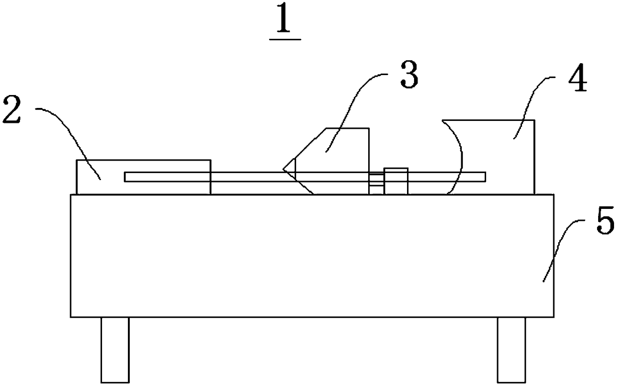
[0033] This embodiment provides a steel bar processing device, which includes a steel bar end grinding mechanism 1, which is mainly used for rapidly grinding the deformed and punctured ends.

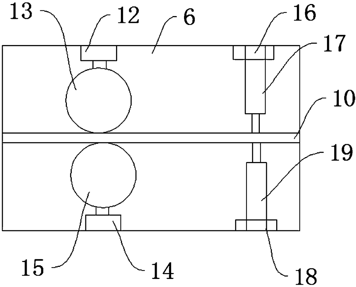
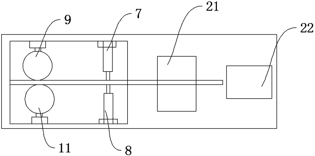
[0034] see Figure 1 to Figure 4 , the steel bar end grinding mechanism 1 includes a positioning fixture 2, a grinding assembly 3, a grinding assembly 4 and a support frame 5; the positioning fixture 2 includes a positioning plate 6, a first clamp 7, a second clamp 8, a first driver 9 and the second driver 11; the positioning plate 6 is provided with a chute 10 in the axial direction, the first clamp 7 and the second clamp 8 are respectively installed on both sides of the chute 10, and the first driver 9 is installed The second driver 11 is respectively installed on one side of the chute 10 opposite to the chute 10, and the steel bar to be processed is arranged in the chute 10; , the grinding assembly 3 and the grinding assembly 4 are on the same straight line; the first driver 9 can dr...


PUM


Abstract

The invention provides a reinforced steel bar end portion polishing mechanism and a reinforced steel bar machining device, and belongs to the technical field of constructional engineering. The reinforced steel bar end portion polishing mechanism comprises a positioning clamp, a polishing assembly, a grinding assembly and a supporting frame; the positioning clamp comprises a positioning board, a first clamp, a second clamp and a first driver; the positioning board is provided with a sliding groove in the axial direction; the first clamp and the second clamp are oppositely installed on two sidesof the sliding groove; the first driver is installed on one side of the sliding groove; reinforced steel bars to be machined are put in the sliding groove; the positioning board, the polishing assembly and the grinding assembly are sequentially installed on the supporting frame and located on the same straight line; and the first driver can drive the reinforced steel bars to make linear reciprocated movement in the length direction of the sliding groove. The reinforced steel bar machining device is simple in structure and convenient and rapid to use.

Description

technical field [0001] The invention relates to the technical field of construction engineering, in particular to a steel bar end grinding mechanism and a steel bar processing device. Background technique [0002] At present, the straight thread connection technology of steel bars is performed by using the rib stripping and rolling process. First, the end of the steel bar is cut flat with a cutting machine; secondly, the end is stripped and rolled with a rolling threading machine; finally, the steel bar is connected with a connecting sleeve. In the actual application process, it is found that end burrs are easily generated during the process of cutting the end of the steel bar with a cutting machine and rolling and stripping the ribbed steel bar with a threader. The port burr, on the one hand, is easy to cut the construction personnel during the construction process; Require. Therefore, the burr at the end of the steel bar must be dealt with. [0003] The conventional tr...

Claims


Application Information

Patent Timeline
IPC IPC(8): B24B9/00B24B9/04B24B41/06B24B41/00B24B27/00B24B47/08B23C3/12
CPCB23C3/12B24B9/00B24B9/04B24B27/00B24B41/005B24B41/067B24B47/08
Inventor 丁杰
Owner NO 2 ENG CO LTD OF CHINA RAILWAY CONSTR 11 BUREAU GRP
Why Eureka
Try Eureka