Substrate edge polishing device for liquid crystal display module production

A technology for liquid crystal display modules and substrates, which is applied to grinding drive devices, grinding/polishing safety devices, machine tools suitable for grinding workpiece edges, etc. It can improve the fixing effect, improve the quality of edging, and improve the work efficiency.

Inactive Publication Date: 2018-10-23
JIANGSU JUTAI TECH CO LTD
View PDF9 Cites 3 Cited by
  • Summary
  • Abstract
  • Description
  • Claims
  • Application Information

AI Technical Summary

Problems solved by technology

[0002] As we all know, the substrate edging device for liquid crystal display module production is an auxiliary device for edging glass substrates cut into corresponding sizes during the production process of liquid crystal display modules. It is used in the fields of display processing and electronic product production. It has been widely used; the existing substrate edging device for liquid crystal display module production includes a workbench, a left support plate, a right support plate, a top plate and a manual edging machine, and the bottom ends of the left support plate and the right support plate are respectively It is connected with the left side and the right side of the top of the workbench, the tops of the left support plate and the right support plate are respectively connected with the left side and the right side of the bottom end of the top plate, the bottom end of the top plate is provided with a compression cylinder assembly, and the compression cylinder assembly The bottom output end is provided with a fixed

Method used


Image

  • Substrate edge polishing device for liquid crystal display module production
  • Substrate edge polishing device for liquid crystal display module production
  • Substrate edge polishing device for liquid crystal display module production

Examples


Example Embodiment

[0017] The specific embodiments of the present invention will be described in further detail below in conjunction with the drawings and embodiments. The following examples are used to illustrate the present invention, but not to limit the scope of the present invention.
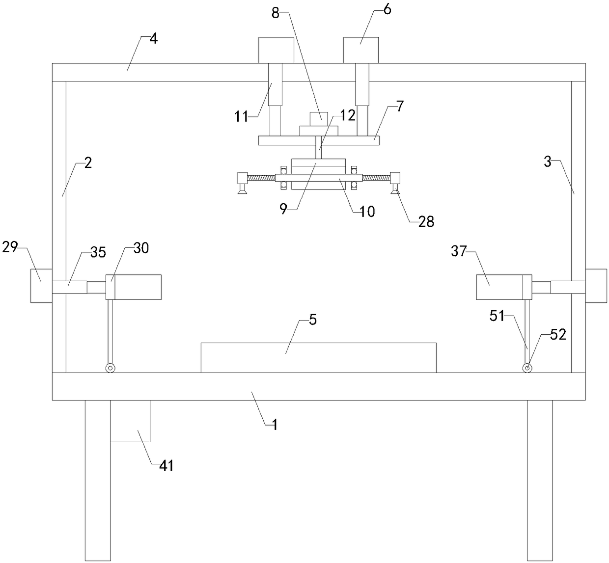
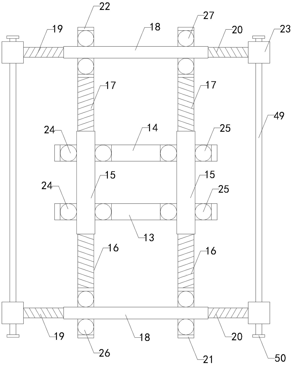
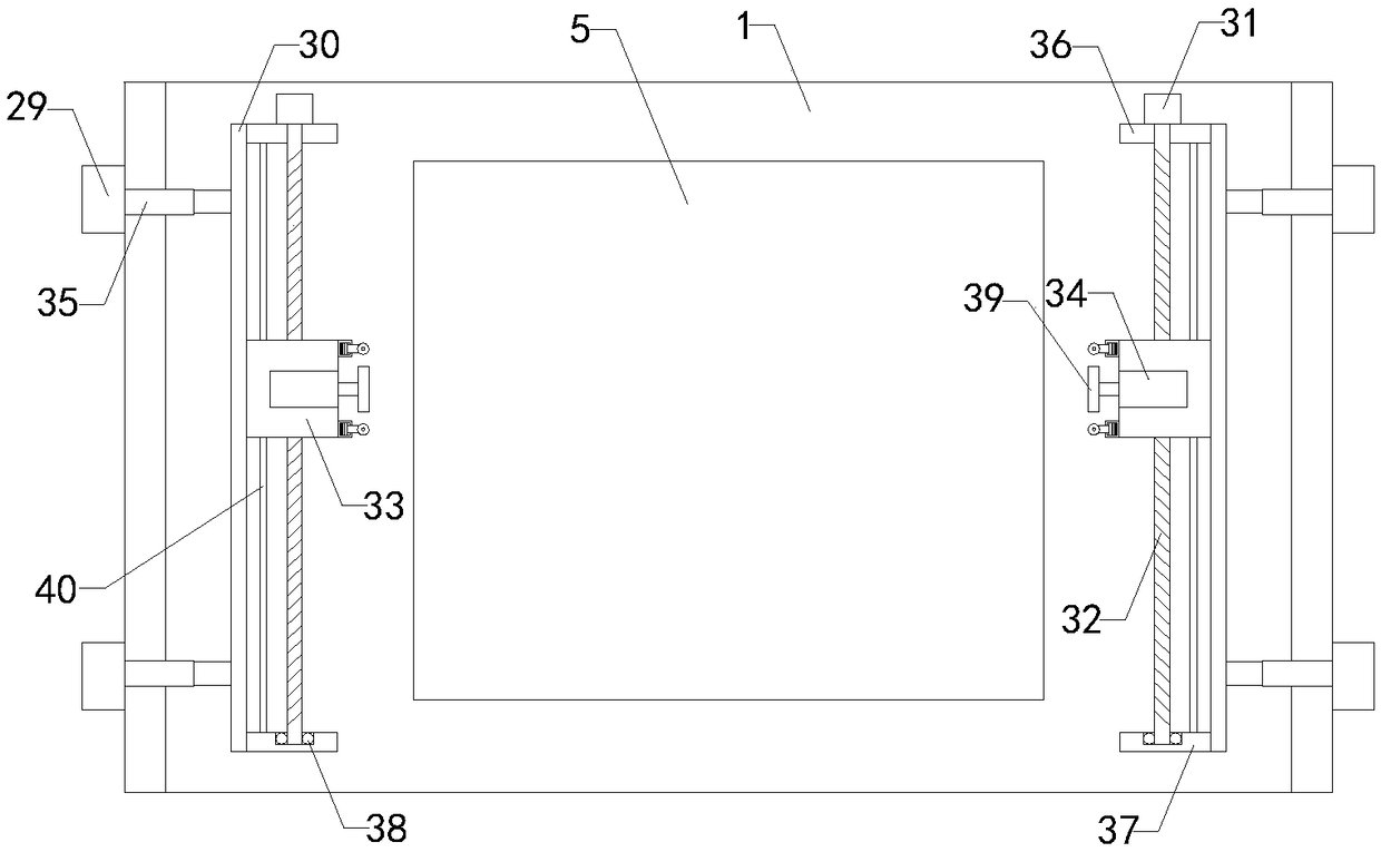
[0018] Such as Figure 1 to Figure 4 As shown, a substrate edging device for the production of liquid crystal display modules of the present invention includes a workbench 1, a left support plate 2, a right support plate 3 and a top plate 4. The bottom ends of the left support plate and the right support plate are respectively connected to the working The left and right sides of the top of the table are connected, the tops of the left and right supporting plates are respectively connected to the left and right of the bottom of the top plate, and the middle of the top of the worktable is provided with a placing table 5; also includes two sets of cylinders 6, fixed Plate 7, stepper motor 8, mounting plate 9 and b...


PUM


Abstract

The invention relates to the technical field of processing of auxiliary devices of liquid crystal displays, and in particular to a substrate edge polishing device for liquid crystal display module production. The substrate edge polishing device improves the fixing effect on glass substrates, prevents the glass substrates from shifting in the edge polishing process and improves the working efficiency. The substrate edge polishing device comprises a workbench, a left supporting plate, a right supporting plate, a top plate, a placing table, an air cylinder, a fixing plate, a stepping motor, a mounting plate, a substrate fixing device, a piston rod and a rotating shaft, wherein the substrate fixing device comprises a front transverse plate, a rear transverse plate, longitudinal threaded tubes,front threaded rods, rear threaded rods, transverse threaded tubes, left threaded rods, right threaded rods, front connecting blocks, rear connecting blocks, mounting blocks, a left ball bearing, a right ball bearing, a front ball bearing, a rear ball bearing and a powerful sucker; and the substrate edge polishing device further comprises a left electric cylinder, a right electric cylinder, a left connecting plate, a right connecting plate, a reciprocating motor, a screw rod, a slider, an edge polishing motor, a left telescopic rod, a right telescopic rod, a rear supporting plate, a front supporting plate, a lower ball bearing and an edge polishing wheel.

Description

technical field [0001] The invention relates to the technical field of liquid crystal display processing accessory devices, in particular to a substrate edge grinding device for liquid crystal display module production. Background technique [0002] As we all know, the substrate edging device for liquid crystal display module production is an auxiliary device for edging glass substrates cut into corresponding sizes during the production process of liquid crystal display modules. It is used in the fields of display processing and electronic product production. It has been widely used; the existing substrate edging device for liquid crystal display module production includes a workbench, a left support plate, a right support plate, a top plate and a manual edging machine, and the bottom ends of the left support plate and the right support plate are respectively It is connected with the left side and the right side of the top of the workbench, the tops of the left support plate...

Claims


Application Information

Patent Timeline
IPC IPC(8): B24B9/10B24B27/00B24B41/06B24B41/02B24B47/12B24B55/00B24B47/06G02F1/13
CPCB24B9/10B24B27/0023B24B27/0076B24B41/02B24B41/06B24B47/06B24B47/12B24B55/00G02F1/1303
Inventor 赵圣铭
Owner JIANGSU JUTAI TECH CO LTD
Why Eureka
Try Eureka