Efficient mixing system for well cementing operation

A mixing system and cementing technology, which is applied to wellbore/well components, control devices, liquid batching supply devices, etc., can solve the problems of low operation efficiency, small mixing displacement, and inability to achieve continuous operation, and achieve convenient and practical operation. , Overcome the effect of reduced mixing capacity

Pending Publication Date: 2018-10-23
YANTAI JEREH PETROLEUM EQUIP & TECH CO LTD
View PDF6 Cites 119 Cited by
  • Summary
  • Abstract
  • Description
  • Claims
  • Application Information

AI Technical Summary

Problems solved by technology

On the other hand, due to the limitation of on-site operating conditions, such as the quality of on-site dry ash, the speed and size of ash supply, etc., the mixing capacity of the mixer is generally within 1.5m 3 / min, the operating efficiency is low, the mixing displacement is small, and continuous operation cannot be realized

Method used


Image

  • Efficient mixing system for well cementing operation
  • Efficient mixing system for well cementing operation
  • Efficient mixing system for well cementing operation

Examples


Embodiment 1

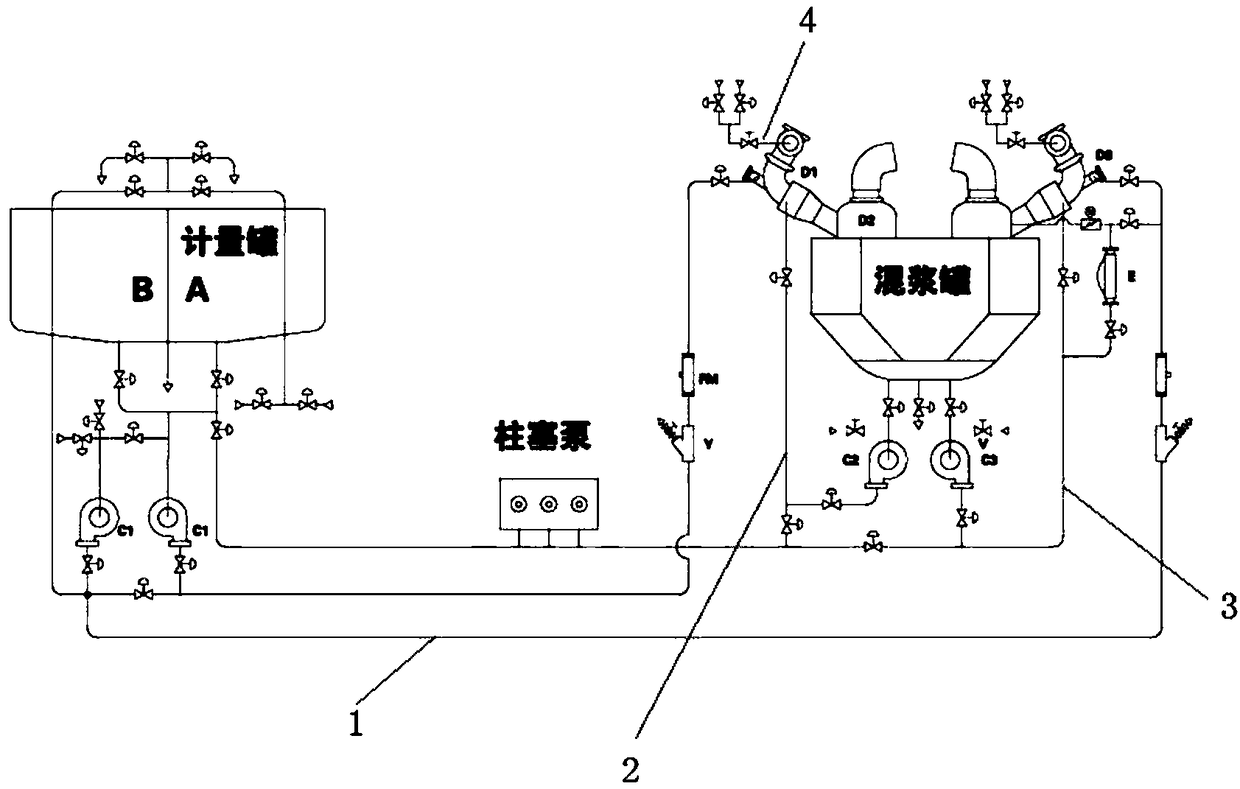
[0026] Such as figure 2 As shown, a mixing system for high-efficiency well cementing operations includes metering tanks, clean water pipes combined into 1, ash loading pipes combined into 4, high-energy mixer D3, mud mixing tanks and mud pipes combined into 3, and the mixing tanks are connected with Two high-energy mixers D3, the entrance of the mixing tank is connected to the diffusion box D2, the diffusion box D2 is connected to the high-energy mixer D3, the output of the high-energy mixer D3 is imported into the mixing tank from the diffusion box D2, and the mud pipes are aggregated into 3 Connect the density control system E in series. There are two diffusion boxes.

[0027] The clean water pipes are aggregated into 1 and equipped with a jet centrifugal pump C1, a Y-shaped filter Y and a clean water flow meter FM. The clean water flow meter FM can display the flow of clean water. According to the displayed clean water flow, the flow can be adjusted according to the desig...

Embodiment 2

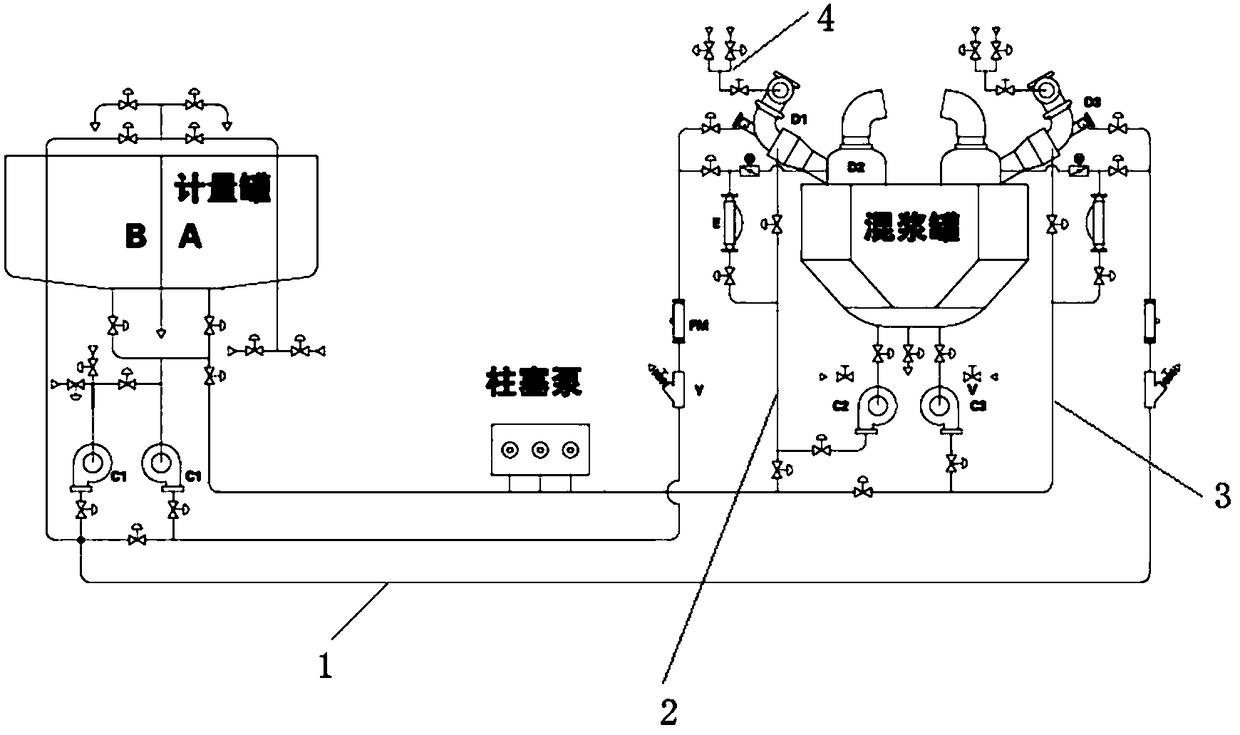
[0034] like image 3 As shown, a mixing system for high-efficiency well cementing operations includes metering tanks, clean water pipes combined into 1, ash loading pipes combined into 4, high-energy mixer D3, mud mixing tanks and mud pipes combined into 3, and the mixing tanks are connected with Two high-energy mixers D3, the entrance of the mixing tank is connected to the diffusion box D2, the diffusion box D2 is connected to the high-energy mixer D3, the output of the high-energy mixer D3 is imported into the mixing tank from the diffusion box D2, and the circulation manifold 2 and the mud pipe are combined into 3, which are all connected in series with a density control system E, and there are two diffusion boxes.

[0035] The clean water pipes are aggregated into 1 and equipped with a jet centrifugal pump C1, a Y-shaped filter Y and a clean water flow meter FM. The clean water flow meter FM can display the flow of clean water. According to the displayed clean water flow, ...

Embodiment 3

[0042] like Figure 4 As shown, a mixing system for high-efficiency well cementing operations includes metering tanks, clean water pipes combined into 1, ash loading pipes combined into 4, high-energy mixer D3, mud mixing tanks and mud pipes combined into 3, and the mixing tanks are connected with Two high-energy mixers D3, the entrance of the mixing tank is connected to the diffusion box D2, the diffusion box D2 is connected to the high-energy mixer D3, the output of the high-energy mixer D3 is imported into the mixing tank from the diffusion box D2, and the mud pipes are aggregated into 3 Connect the density control system E in series. The diffusion box is one.

[0043] The clean water pipes are aggregated into 1 and equipped with a jet centrifugal pump C1, a Y-shaped filter Y and a clean water flow meter FM. The clean water flow meter FM can display the flow of clean water. According to the displayed clean water flow, the flow can be adjusted according to the design requir...


PUM


Abstract

The invention relates to the technical field of petroleum equipment, in particular to an efficient mixing system for well cementing operation. The efficient mixing system comprises a measuring tank, aclear water manifold assembly, a cement grey feeding manifold assembly, high-energy mixers, a mud mixing tank and a mud manifold assembly. The mud mixing tank is at least connected with two high-energy mixers, and an inlet of the mud mixing tank is connected with diffusion boxes which are connected with the high-energy mixers. Discharged materials of the high-energy mixers are guided into the mudmixing tank through the diffusion boxes, and the at least one diffusion box is connected with a density control system. The multiple sets of mixers are integrated, and the large-discharge-capacity and efficient mixing effect can be achieved with existing operation conditions.

Description

technical field [0001] The invention relates to the technical field of petroleum equipment, in particular to a mixing system for high-efficiency well cementing operations. Background technique [0002] According to reports, the drilling cycle of the oil field industry has been reduced from 175 days to about half of 75 days; while the US shale gas has increased efficiency by 40% since 2013. With the improvement of the operating efficiency of the oilfield industry, the emergence of ultra-deep wells and the increase of the distance of solidified casing, for example, the horizontal section can only be 1000 meters in the past, and the buried depth can only be 2500 meters. Now the horizontal section can be 2500 meters. meters, and the buried depth increased to more than 4,300 meters. Such operations also put forward higher and higher requirements for large-volume cementing operations. On the other hand, due to the limitation of on-site operating conditions, such as the quality of...

Claims


Application Information

Patent Timeline
Patent Type & Authority Applications(China)
IPC IPC(8): B28C5/08B28C7/02B28C7/12E21B33/13
CPCE21B33/13B28C5/08B28C5/0806B28C7/02B28C7/128
Inventor 王彦峰刘仁李恩杰刘士堂李心成崔树桢刘光宇贾芝李明升袁寅龙
Owner YANTAI JEREH PETROLEUM EQUIP & TECH CO LTD
Why Eureka
Try Eureka