Method and system for boosted engine system

A technology of engines and compressors, applied in the direction of combustion engines, engine control, machines/engines, etc., can solve problems such as reduced drivability, engine performance damage, reduced vehicle start-up quality, and driver satisfaction

Active Publication Date: 2018-10-23
FORD GLOBAL TECH LLC
View PDF5 Cites 1 Cited by
  • Summary
  • Abstract
  • Description
  • Claims
  • Application Information

AI Technical Summary

Problems solved by technology

Among other things, the instantaneous peak acceleration at vehicle launch (eg, during the first second) can be limited, reducing vehicle launch quality and driver satisfaction
Additionally, NVH issues that reduce drivability (such as howling) can be experienced upon tip-in
Engine performance can be compromised if boost pressure is reduced to address tip-in

Method used


Image

  • Method and system for boosted engine system
  • Method and system for boosted engine system
  • Method and system for boosted engine system

Examples


Embodiment Construction

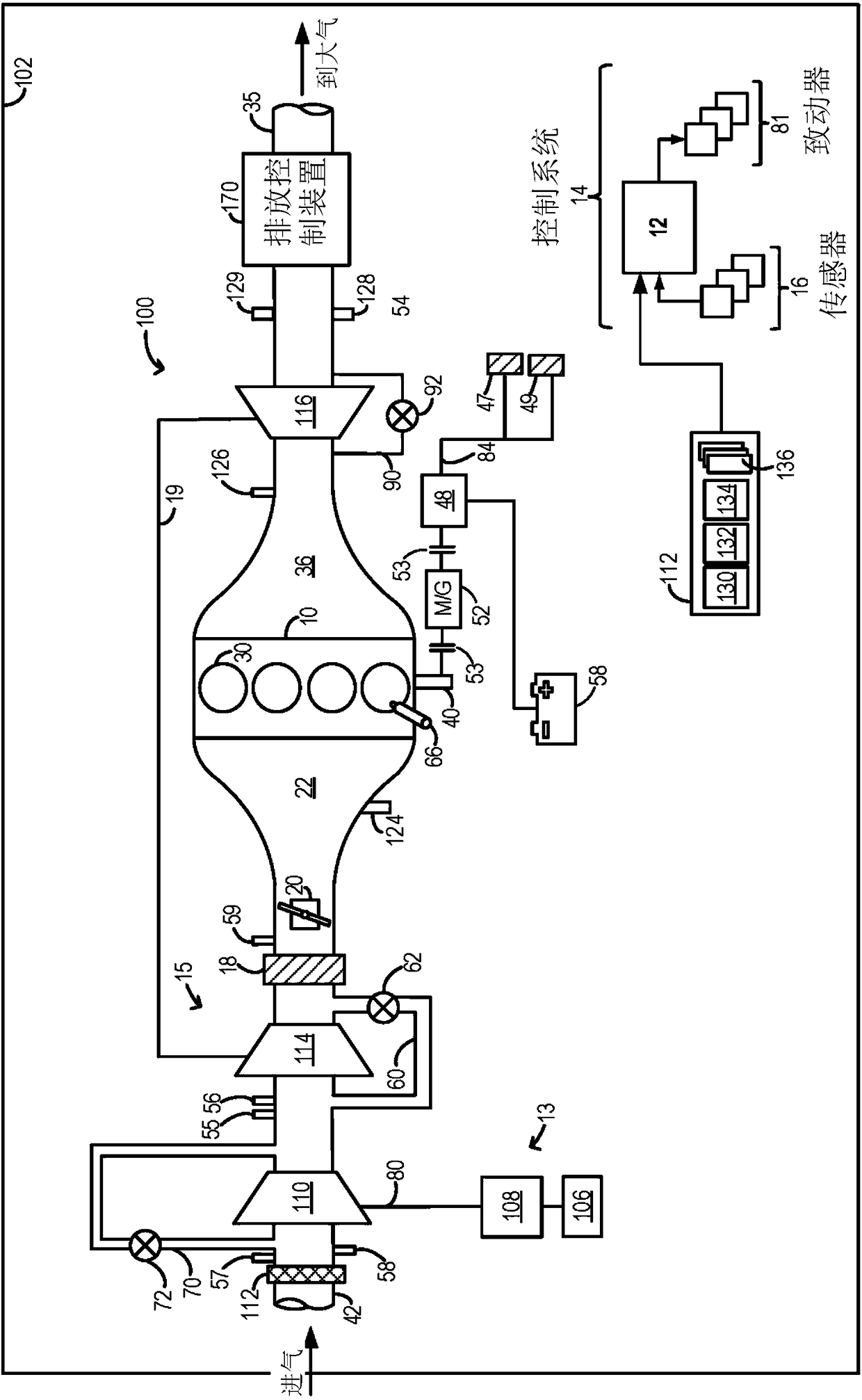
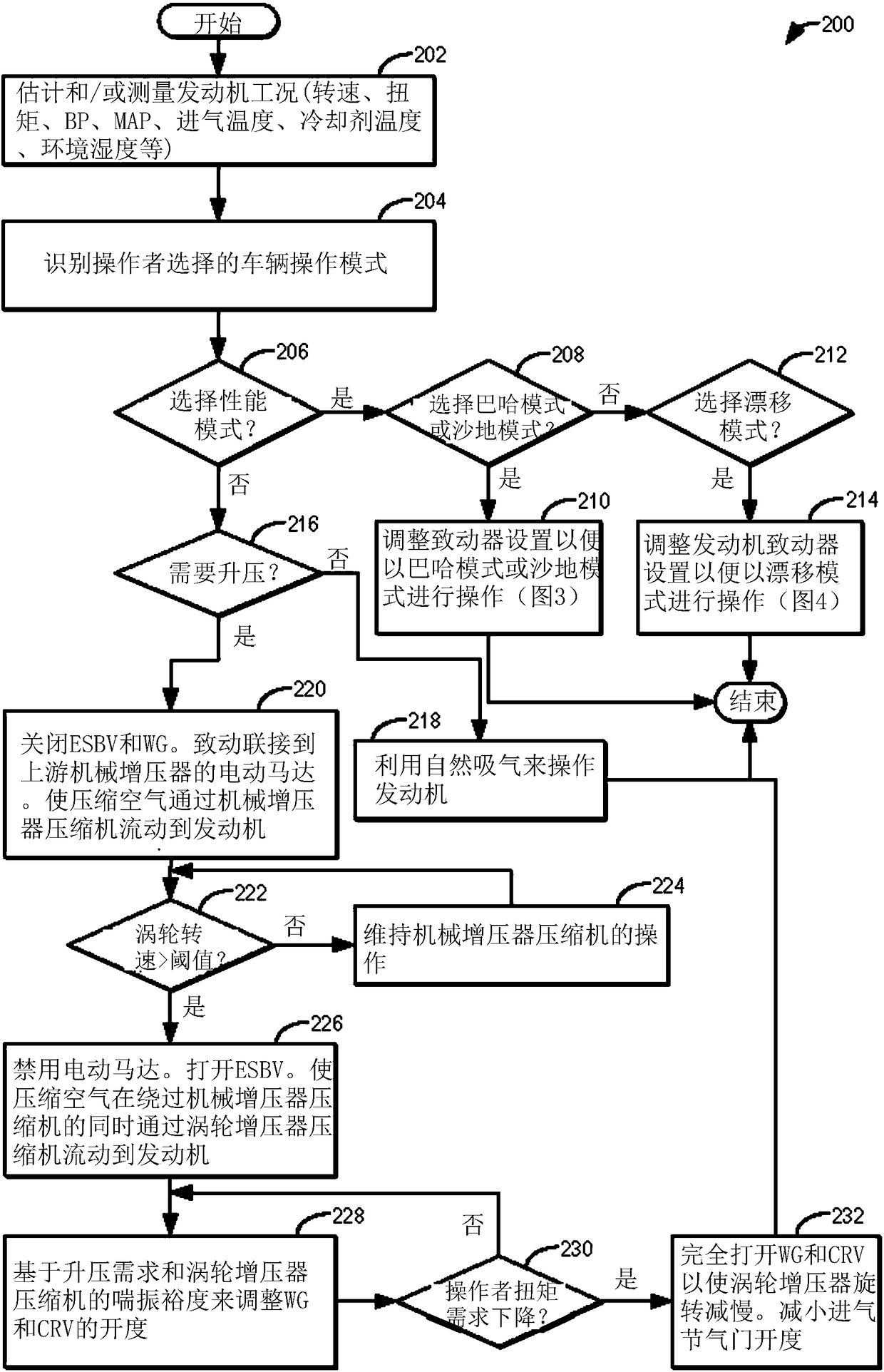
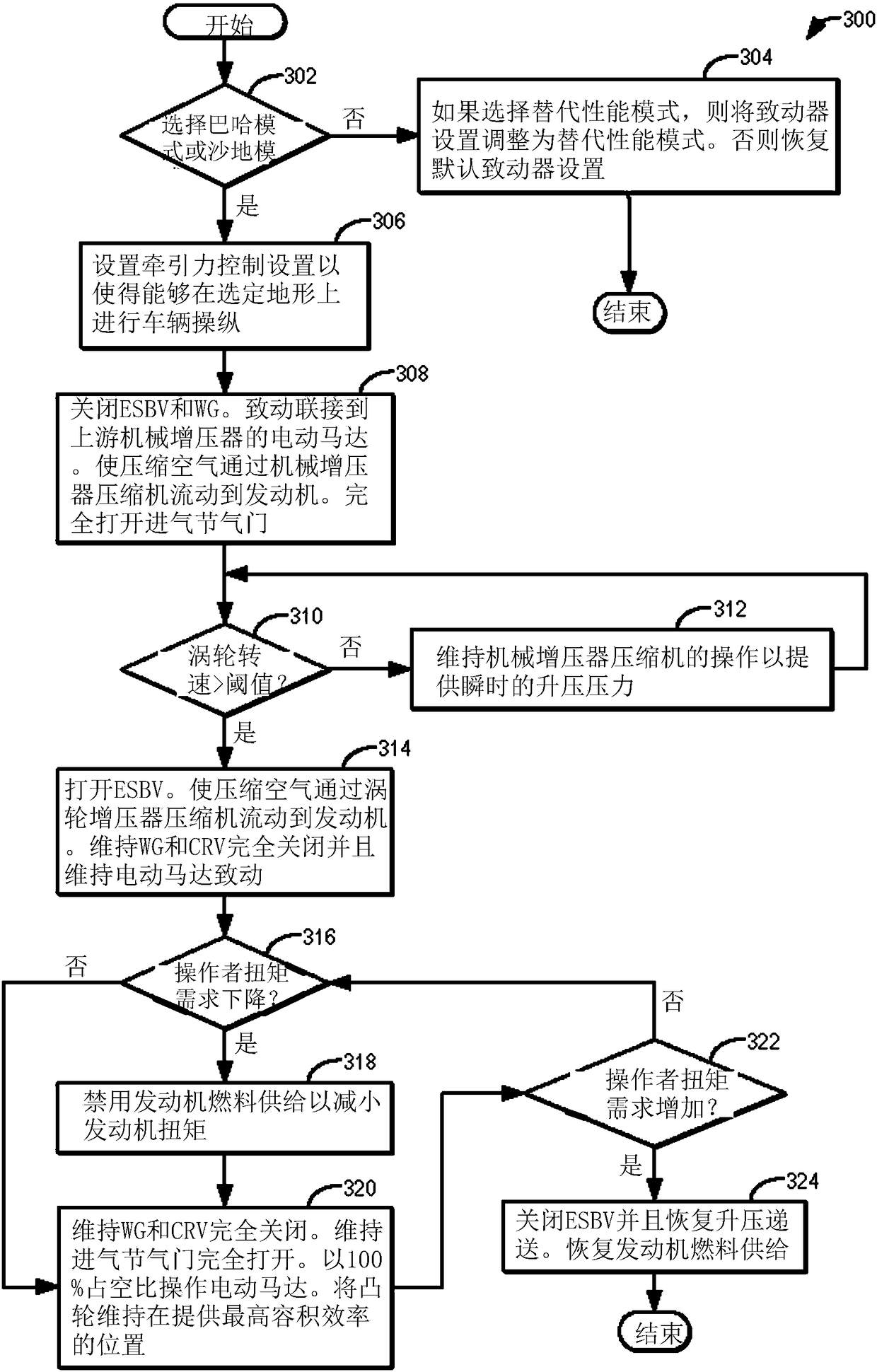
[0015] The following description pertains to use in engine systems with stepped boosting devices, such as in figure 1 A system and method for improving transient boost response during execution of vehicle maneuvers in a boosted engine system. The controller can be configured to execute control programs such as Figure 2 to Figure 4 example program) to adjust air paths and engine torque actuator settings based on the operator-selected performance mode to improve torque response during various vehicle maneuvers. refer to Figure 5 to Figure 6 Predicted engine operation is shown. Improved engine torque response by adjusting actuator settings so that manifold pressure can be maintained elevated above atmospheric pressure independent of changes (e.g., increases or decreases) in torque demand, thereby enhancing engine torque response in various performance modes Vehicle drivability.

[0016] figure 1 Aspects of an example engine system 100 including engine 10 coupled in a vehic...


PUM


Abstract

The invention relates to a method and system for a boosted engine system. Methods and systems are provided for increasing vehicle maneuverability when operating on sand, snow, or rocky terrain, as well as while performing cornering and sliding maneuvers. Boost path actuators are held in positions that enable manifold pressure to be held above barometric pressure as torque demand changes, includingwhen torque demand drops. Engine torque is reduced or raised via adjustments to one or more of fuel delivery, spark timing, and intake throttle opening.

Description

technical field [0001] The present description generally relates to methods and systems for improving transient response in boosted engine systems. Background technique [0002] Engines may be configured with boosting devices, such as turbochargers or superchargers, to increase air mass flow into the combustion chambers. Turbochargers and superchargers use an intake compressor to compress the intake air entering the engine. While a turbocharger includes a compressor driven by a turbine, a supercharger includes a compressor driven by an engine or motor. In some engine systems, one or more intake boost devices may be staged in series or parallel to improve engine boost response. [0003] An example of a multi-stage booster engine is shown in US Patent 6,938,420 by Kawamura et al. Among them, an electric supercharger driven by an electric motor and an electric supercharger bypass valve (ESBV) are staged downstream of the turbocharger. During conditions where the turbocharge...

Claims


Application Information

Patent Timeline
Patent Type & Authority Applications(China)
IPC IPC(8): F02B37/04F02B37/16F02B37/18F02D23/02F02D41/00
CPCF02B37/162F02B37/04F02B37/16F02B37/18F02D23/02F02D41/0007F02B2037/125F02D2200/606F02D41/0005F02D41/0087F02D41/107F02D41/123F02D41/1497F02D2200/0406F02D2200/602F02D2200/604F02B37/14F02B2037/122Y02T10/12Y02T10/40F02B37/10B60K6/20
Inventor 肖柏韬J·E·M·赫尔斯特伦A·N·班克
Owner FORD GLOBAL TECH LLC
Why Eureka
Try Eureka