Vibration reduction method and system for low frequency elastic waves, and vibration reduction device
A vibration damping device and elastic wave technology, applied in the functional characteristics of spring/shock absorber, shock absorber, spring/shock absorber, etc., can solve the problem of not meeting the requirements of invariance, unable to meet the design conditions of winding materials, Does not have immutability and other issues
- Summary
- Abstract
- Description
- Claims
- Application Information
AI Technical Summary
Problems solved by technology
Method used
Image

Examples
Embodiment 1
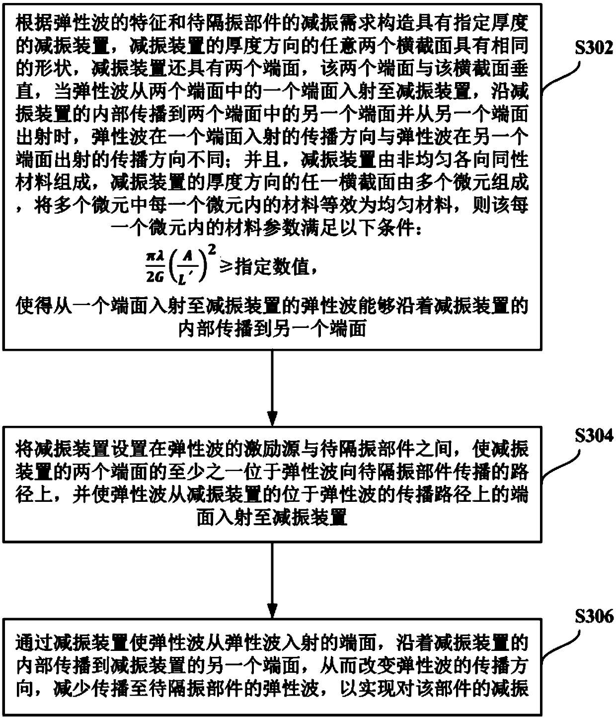
[0129] The vibration reduction method for low-frequency elastic waves in the embodiment of the present invention is suitable for reducing the vibration of the component to be isolated caused by the elastic waves generated by the excitation source, and the specific solution includes the following steps a) to c).
[0130] a) Construct a vibration damping device with a specified thickness according to the characteristics of the elastic wave and the vibration damping requirements of the parts to be isolated. Any two cross sections in the thickness direction of the vibration damping device have the same shape, and the shape of the cross section is a semicircle Annular, the vibration damping device also has two end faces, the two end faces are perpendicular to the cross section, when the elastic wave is incident on the vibration damping device from one of the two end faces, it propagates along the interior of the vibration damping device to the two end faces When the other end face i...
Embodiment 2
[0139] The specific scheme of the vibration damping method for low-frequency elastic waves in the embodiment of the present invention is the same as in Embodiment 1, except that the vibration damping device is constructed in the following manner in this embodiment:
[0140] The first step is to select the first rubber and mold the first rubber to obtain a semi-circular matrix with a specified thickness, wherein the first Lamé constant and the second Lamé constant of the first rubber are λ 1 , G 1 .
[0141] In the second step, select the second rubber, the first Lamé constant and the second Lamé constant of the second rubber are λ 2 , G 2 , where λ 2 1 , G 2 1 .
[0142] In the third step, a plurality of columns of through holes arranged radially are formed on the semi-circular substrate according to predetermined rules.
[0143] Figure 8 It shows a schematic diagram of the distribution of multiple columns of through holes formed on the semi-annular substrate according...
Embodiment 3
[0146] The specific scheme of the vibration damping method for low-frequency elastic waves in the embodiment of the present invention is the same as in Embodiment 1, except that the vibration damping device is constructed in the following manner in this embodiment:
[0147] The first step is to select the first rubber and mold the first rubber to obtain a semi-circular matrix with a specified thickness, wherein the first Lamé constant and the second Lamé constant of the first rubber are λ 1 , G 1 .
[0148] In the second step, select the second rubber, the first Lamé constant and the second Lamé constant of the second rubber are λ 2 , G 2 , where λ 2 1 , G 2 1 .
[0149] In the third step, multiple rows of through holes arranged in parallel are formed on the semi-circular base according to predetermined rules.
[0150] Figure 9 It shows a schematic diagram of the distribution of multiple rows of through holes formed on the semi-annular substrate according to predetermi...
PUM
 Abstract
Description
Claims
Application Information
 - R&D
- Intellectual Property
- Life Sciences
- Materials
- Tech Scout
- Unparalleled Data Quality
- Higher Quality Content
- 60% Fewer Hallucinations
Browse by: Latest US Patents, China's latest patents, Technical Efficacy Thesaurus, Application Domain, Technology Topic, Popular Technical Reports.
© 2025 PatSnap. All rights reserved.Legal|Privacy policy|Modern Slavery Act Transparency Statement|Sitemap|About US| Contact US: help@patsnap.com