Clamping device for testing wheel hub motor, and testing method for clamping device

A technology of in-wheel motors and clamping devices, which is applied in the direction of motor generator testing, etc., can solve the problems that the fixtures cannot be applied to in-wheel motors of different specifications, the structure of the fixture is complicated, and the installation is inconvenient, so as to achieve fast testing, improve versatility, and install convenient effect

Pending Publication Date: 2018-10-23
GUANGDONG MECHANICAL & ELECTRICAL COLLEGE
View PDF0 Cites 4 Cited by
  • Summary
  • Abstract
  • Description
  • Claims
  • Application Information

AI Technical Summary

Problems solved by technology

[0003] The purpose of the present invention is to solve the problem that the existing fixtures used for testing wheel hub motors have complex structures and inconvenient installation, and the fixtures cannot be used wi

Method used


Image

  • Clamping device for testing wheel hub motor, and testing method for clamping device
  • Clamping device for testing wheel hub motor, and testing method for clamping device
  • Clamping device for testing wheel hub motor, and testing method for clamping device

Examples


Embodiment

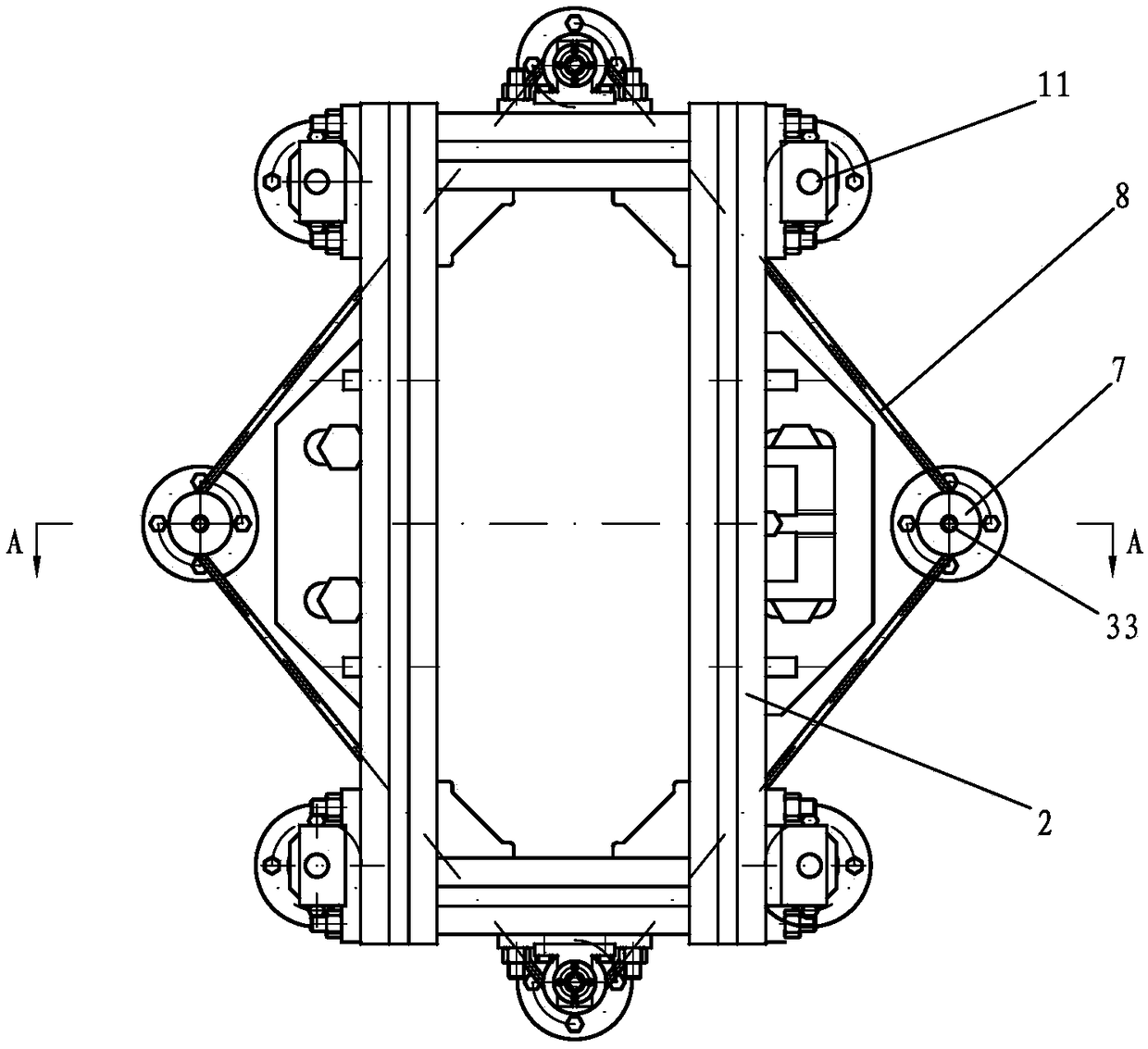
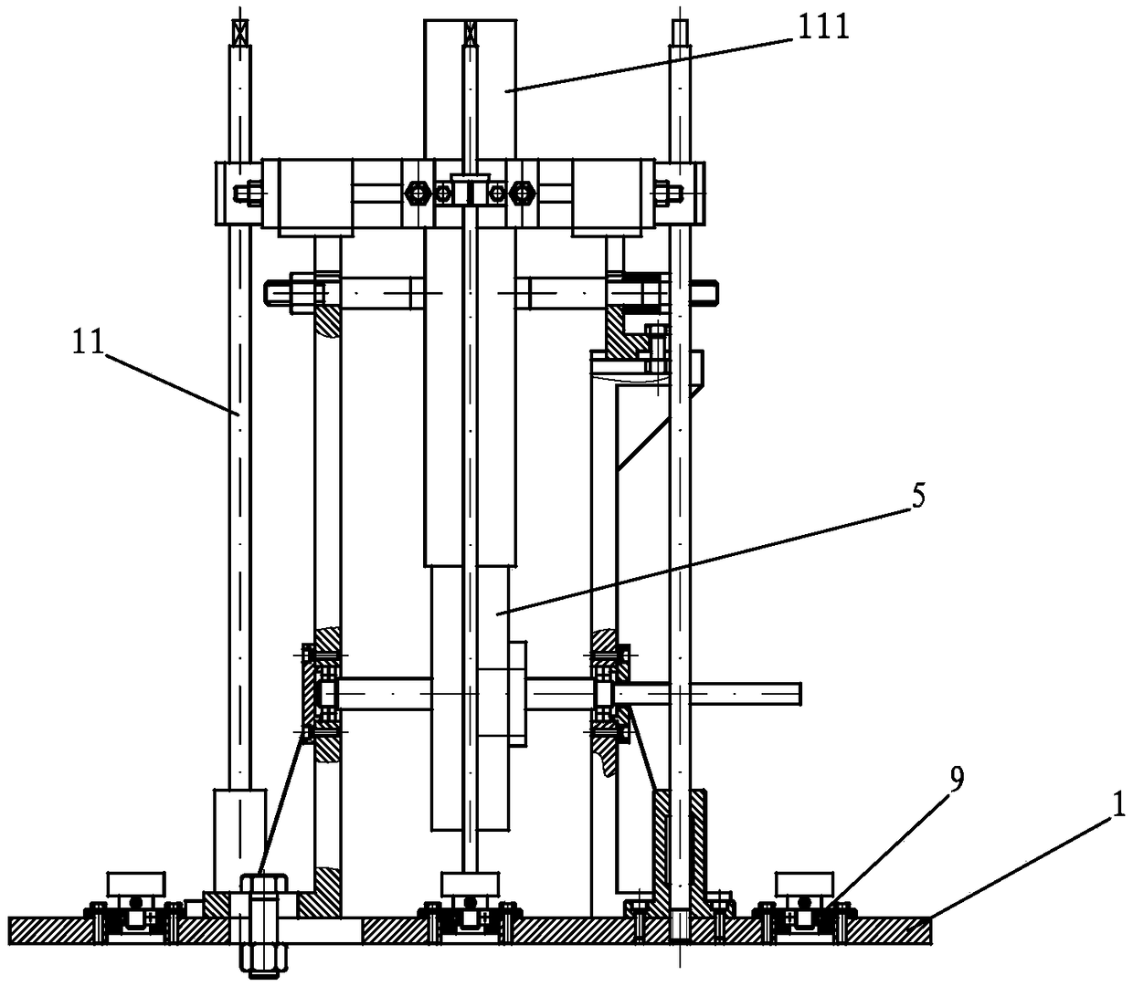
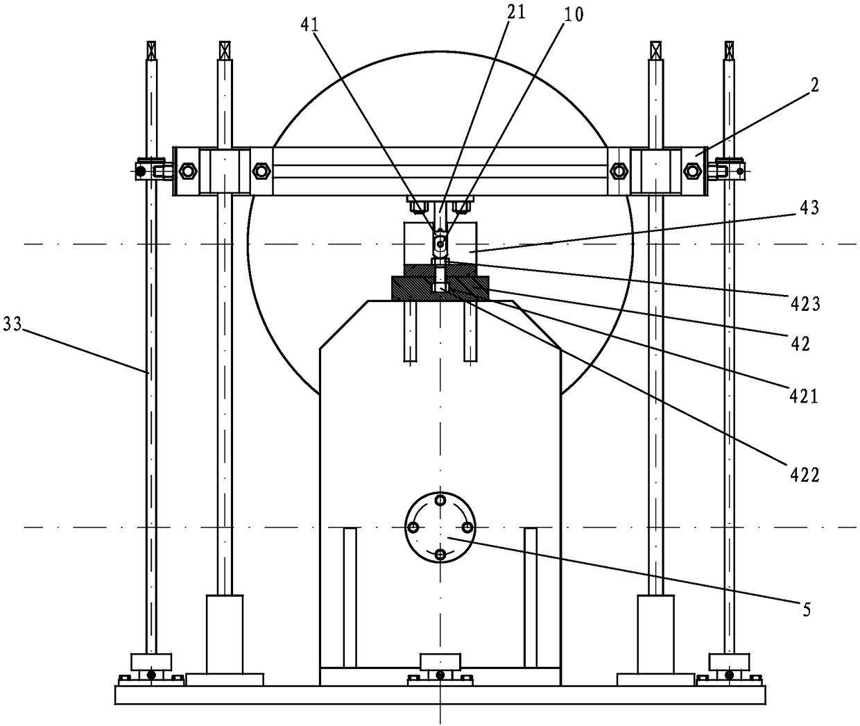
[0029] see Figure 1 to Figure 3 , the present embodiment relates to a test clamping device, including a base 1, a sliding frame 2, and a driving device 3. Several guide rods 11 are vertically installed on the base 1, and the sliding frame 2 is slidably sleeved on the guide rods. 11; a support 4 is installed on both sides of the base 1, and the support 4 is provided with a groove 41 for placing the hub motor shaft 10; the power output end of the driving device 3 is connected to the sliding The frame 2 is connected to drive the pressing device to slide on the guide rod 11, the friction wheel 5 is rotatably installed on the support 4, and the pressing block corresponding to the position of the groove 41 is fixedly installed on the sliding frame 2 21. When the driving device 3 drives the sliding frame 2 to slide downward, the pressing block 21 is inserted into the groove 41 to press the in-wheel motor shaft 10 rotatably in the groove 41, and the outer circle of the in-wheel motor...


PUM


Abstract

The invention discloses a clamping device for testing a wheel hub motor, and the device comprises a pedestal, a sliding frame, and a drive apparatus. The pedestal is vertically provided with a plurality of guide rods, and the sliding frame is slidingly disposed on the guide rods in a sleeving manner. Two sides of the pedestal are provided with support seats, and the support seats are provided withgrooves for placing a wheel hub motor shaft. A power output end of the drive apparatus is connected with the sliding frame so as to drive a compressing apparatus to slide on the guide rods. The support seats are rotatingly provided with a friction wheel, and the sliding frame is fixedly provided with press blocks corresponding to the grooves. When the drive apparatus drives the sliding frame to slide downwards, the press blocks are inserted into the grooves to enable the wheel hub motor shaft to be rotatingly pressed in the grooves. Moreover, the outer circular surface of the wheel hub motorjacks the outer circular surface of the friction wheel. The friction wheel is externally connected with a rotating speed and torque testing apparatus. The device can quickly measure the rotating speedand torque of the wheel hub motor, is simple in structure, is convenient to install, and is quick in testing.

Description

technical field [0001] The invention relates to a clamping device and a testing method thereof, in particular to a hub motor test clamping device and a testing method thereof. Background technique [0002] In-wheel motor technology is also known as in-wheel motor technology. Its biggest feature is that it integrates the power device, transmission device and braking device into the wheel hub, which greatly simplifies the mechanical part of the electric vehicle. After the hub motor is manufactured, it needs to be tested for its rotational torque and speed data to ensure that the performance and quality of the product meet the requirements. Currently, the jig used for testing hub motors has a complex structure and is inconvenient to install, and the jig cannot be used for hub motors of different specifications, and its versatility is poor. Contents of the invention [0003] The purpose of the present invention is to solve the problem that the existing fixtures used for testi...

Claims


Application Information

Patent Timeline
IPC IPC(8): G01R31/34
CPCG01R31/34
Inventor 肖启瑞
Owner GUANGDONG MECHANICAL & ELECTRICAL COLLEGE
Why Eureka
Try Eureka