Switching circuit, system and method for control power of battery swap station, controller and medium

A technology for controlling power supply and switching circuits, which is applied to circuit devices, emergency power supply arrangements, electrical components, etc., and can solve the problems of large volume of ATS automatic transfer switches, easy adhesion of main contacts of electromagnetic contactors, and burnout of electromagnetic contactors, etc. , achieve good overload and short circuit protection function, improve safety and reliability, and ensure continuity

Active Publication Date: 2018-10-23
NIO ANHUI HLDG CO LTD
View PDF6 Cites 2 Cited by
  • Summary
  • Abstract
  • Description
  • Claims
  • Application Information

AI Technical Summary

Problems solved by technology

[0004] (1) The main contact of the electromagnetic contactor of the double miniature circuit breaker double electromagnetic contactor switching method is always in the closed state, and most of the load is the inductive load of the motor. When running for a long time, the main contact of the electromagnetic contactor is easy Adhesion, and then burn out the electromagnetic contactor, easy to cause failure
[0005] (2) The ATS automatic transfer switch of the ATS automatic transfer switch method is bulky, difficult to install and arrange, and the price is high

Method used


Image

  • Switching circuit, system and method for control power of battery swap station, controller and medium
  • Switching circuit, system and method for control power of battery swap station, controller and medium
  • Switching circuit, system and method for control power of battery swap station, controller and medium

Examples


example 1

[0073] Example 1. Normal situation

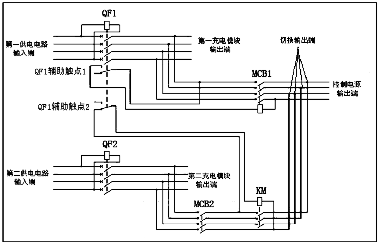
[0074] The first transformer and the second transformer both have power and are in normal state. Close the molded case circuit breaker QF1, molded case circuit breaker QF2, miniature circuit breaker MCB1, and miniature circuit breaker MCB2 respectively; when closing the molded case circuit breaker QF1, QF1 assists Contact 1 is closed from the normally open state, the coil of the undervoltage release of the miniature circuit breaker MCB1 is energized, and the coil of the undervoltage release of the miniature circuit breaker MCB1 is energized before the miniature circuit breaker MCB1 can be closed manually; When the shell circuit breaker is QF1, the auxiliary contact 2 of QF1 turns from normally closed to open, the coil circuit of the electromagnetic contactor KM has a disconnection point, and the main contact of the electromagnetic contactor KM will be in the disconnected state. In this case, the first power supply circuit and the second pow...

example 2

[0075] Example 2: Abnormal situation of the first power supply circuit

[0076] Assuming that the first transformer is powered off, the molded case circuit breaker QF1 will automatically disconnect due to the configuration of a voltage-loss release. The buckle coil is de-energized, the miniature circuit breaker MCB1 is disconnected; the auxiliary contact 2 of QF1 turns from the disconnected state to the closed state, the coil of the electromagnetic contactor KM is energized, and the main contact of KM turns from the disconnected state to the closed state. The first power supply circuit is disconnected, and the second power supply circuit supplies power for the control power supply, and the electric energy of the control power supply is taken from the second transformer, such as Figure 7 shown.

example 3

[0077] Example 3: Abnormal Elimination of the First Power Supply Circuit

[0078] When the abnormal situation of the first power supply circuit is eliminated, the first transformer is re-energized, the coil of the voltage loss release of the molded case circuit breaker QF1 is energized, the molded case circuit breaker QF1 is closed, and the auxiliary contact 1 of QF1 turns from the open state to the closed state , the coil of the miniature circuit breaker MCB1 undervoltage release is energized; the auxiliary contact 2 of QF1 turns from the closed state to the open state, the coil circuit of the electromagnetic contactor KM loses power, and the main contact of the electromagnetic contactor KM changes from the closed state Turn to the disconnected state, then close the miniature circuit breaker MCB1, and switch back to the normal working state of the first power supply circuit and the second power supply circuit, the electric energy of the control power supply is taken from the f...


PUM


Abstract

The invention relates to a switching circuit, system and method for the control power of a battery swap station, a controller and a medium. The switching circuit comprises a first power supply circuitand a second power supply circuit, wherein the input end of the first power supply circuit is connected to a first transformer, and then is successively connected with a first circuit breaker, a second circuit breaker and a control power output end; the control power output end is used for outputting electric energy for powering each device of the battery swap station; the input end of the secondpower supply circuit is connected with a second transformer, and then is successively connected with an electromagnetic contactor and a switching output end; the switching output end is connected tothe control power output end; the normally open contact of the first circuit breaker is connected in series with the no-voltage release coil circuit of the second circuit breaker; and the normally closed contact of the first circuit breaker is connected in series with an electromagnetic contactor coil circuit. The switching circuit automatically, safely and reliably switches the control power of an electric vehicle battery swap station at low cost.

Description

technical field [0001] The invention relates to the technical field of electric vehicle swapping stations, in particular to a switching circuit, a system, a method, a controller and a medium for controlling a power supply of a swapping station. Background technique [0002] With the rapid development of the electric vehicle industry, more and more electric vehicle replacement stations have settled in cities. During the construction of the substation, in order to minimize investment and avoid repeated construction of transformers and lines, the self-built transformers will be given priority to provide power for the substation, because the built transformers usually have a surplus. However, the built-up transformer margin is generally not very large, and the margin of one transformer is generally not enough to meet the load requirements of the substation. Therefore, the power of the substation is usually taken from two different built transformers. After the two transformer l...

Claims


Application Information

Patent Timeline
Patent Type & Authority Applications(China)
IPC IPC(8): H02J9/06
CPCH02J9/06
Inventor 万兵兵吴广涛
Owner NIO ANHUI HLDG CO LTD
Why Eureka
Try Eureka