
Pinion shaft, clockwork, clock or measuring device without magnetic signature

A pinion shaft, measuring instrument technology, applied in the direction of gear mechanism, frequency stabilization mechanism, frequency stabilization mechanism, etc., can solve problems such as no known

Pending Publication Date: 2018-10-23
OMEGA SA
View PDF10 Cites 0 Cited by
  • Summary
  • Abstract
  • Description
  • Claims
  • Application Information

AI Technical Summary

Problems solved by technology

Thus, no watches are known so far which meet the STANAG 2897 standard and at the same time the NIHS 91-10 standard for shock resistance and / or which after 6 months of running Accuracy required by NHIS90-10 of the table

Method used


Image

  • Pinion shaft, clockwork, clock or measuring device without magnetic signature
  • Pinion shaft, clockwork, clock or measuring device without magnetic signature
  • Pinion shaft, clockwork, clock or measuring device without magnetic signature

Examples


Embodiment Construction

[0033] The following describes how to successfully manufacture a watch, a watch mechanism and a shaft for a watch mechanism having a relative magnetic permeability of less than 1.01, or individual parts thereof. Here, it is realized that all individual components have a relative magnetic permeability of less than 1.0100. Preferably, the relative permeability is between 0.99 and 1.01 or 1.0100. The watch is preferably a wristwatch or a pocket watch, but the watch mechanism can also be incorporated in other watches. If a non-magnetic material or component is mentioned below, this means a material or component with a relative magnetic permeability of less than 1.01, preferably less than 1.0100.

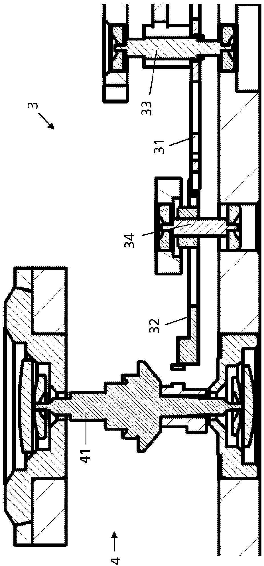
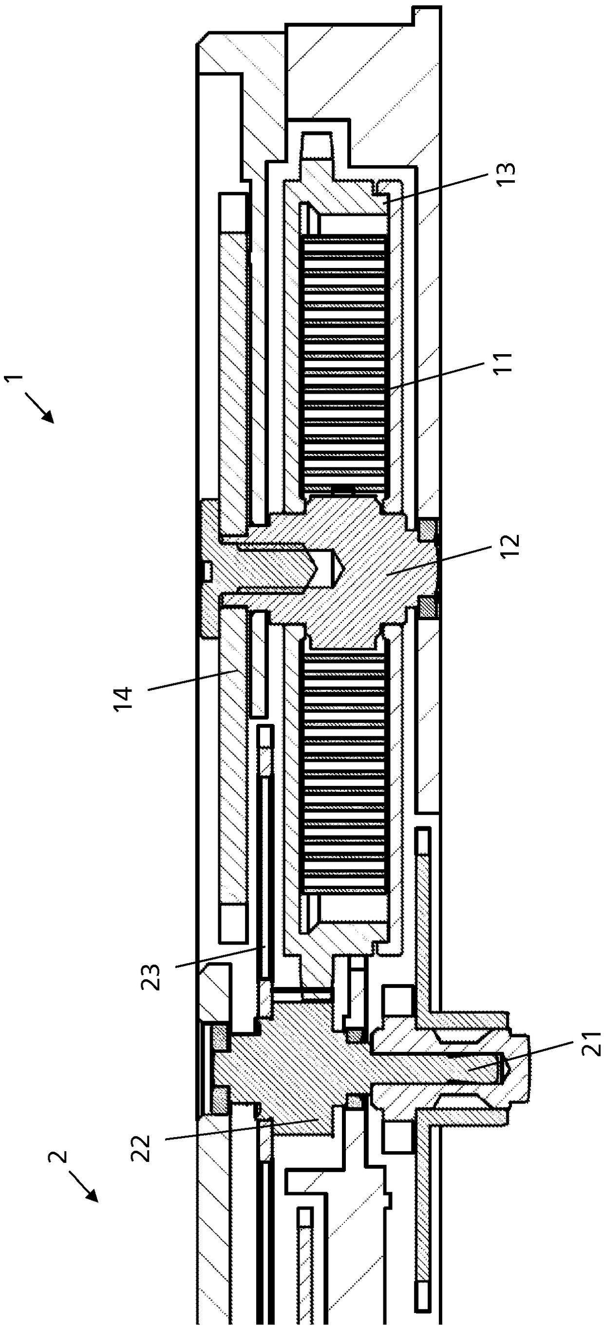
[0034] The watch mechanism has a travel time mechanism and an optional additional mechanism. figure 1 shows a cross-section of one embodiment of such a watch mechanism, while figure 2 with image 3 show figure 1 The enlarged part.

[0035] The travel time mechanism has a driving m...


PUM

PropertyMeasurementUnit
hardnessaaaaaaaaaa
thicknessaaaaaaaaaa
hardnessaaaaaaaaaa

Abstract

The invention relates to a mechanical clock or measuring instrument having metal parts, wherein each part of the mechanical clockwork has a relative magnetic permeability of less than 1.01.

Description

technical field [0001] The present invention relates to a watch mechanism, a watch and a measuring device without magnetic features as well as a method and an axel for the manufacture of said watch mechanism, watch and measuring device without magnetic features. Background technique [0002] There are certain situations where any magnetism is undesirable or even dangerous. For example, in the field of explosive ordnance clearance, even a weak magnetic field is sufficient to trigger the induction detonation device of a bomb or landmine. Therefore, the NATO standard STANAG 2897 for the inspection of non-magnetic tools used in the field of explosive ordnance clearance requires a total magnetic signature of at most 5 nT (nano Tesla). [0003] Electronic or mechanical watches with metal parts according to the prior art always have magnetic features. The current flow of a digital or quartz watch produces a relatively high magnetic field for these conditions and thus a strong mag...

Claims


Application Information

Patent Timeline
Patent Type & Authority Applications(China)
IPC IPC(8): G04B13/00G04B29/02G04B17/32C22C9/00C22C19/07C22C30/00C23C18/34G04B43/00G04B31/008G04B37/22G04B15/14
CPCC22C30/00C23C18/32C22C19/07C22C9/00C22C9/06C22C14/00C22C38/44C22C38/42C22C38/04C22C38/02C22C38/58C22C38/001G04B13/02G04B29/027G04B17/32G04B43/007G04B31/008G04B37/22G04B15/14B32B15/01B32B15/20C22C19/03C22C38/00C23C18/34C22C9/04C22C38/18C22C38/20C22C38/22C22C38/38C25D7/00G04B17/285C25D7/005G04B13/00
Inventor G·高格伊
Owner OMEGA SA
Learn More