Three-dimensional reconstruction method, system and device based on aerial photography of unmanned aerial vehicles

A three-dimensional reconstruction and UAV technology, applied in the field of three-dimensional reconstruction based on UAV aerial photography, can solve the problems of labor-intensive, time-consuming, and large amount of calculation of the three-dimensional model, and achieve the effect of easy operation and simple implementation process.

Active Publication Date: 2018-10-23
SZ DJI TECH CO LTD
View PDF7 Cites 36 Cited by
  • Summary
  • Abstract
  • Description
  • Claims
  • Application Information

AI Technical Summary

Problems solved by technology

[0003] In one solution, the 3D model of the surveying area can be generated by manual point-by-point measurement. However, this method is quite labor-intensive and has great limitations. At the same time, the sampling density is limited, which affects the accuracy of the 3D model; in another In the scheme, 3D reconstruction software can be used to generate a 3D model of the surveying and mapping area through aerial images. However, the process of generating a 3D model requires a large amount of computation, so the 3D reconstruction software needs to be installed on a large computer. At the same time, the process of generating a 3D model is time-consuming It is also long, so it can be seen that the 3D model of the surveying and mapping area obtained through this scheme is not portable and real-time

Method used


Image

  • Three-dimensional reconstruction method, system and device based on aerial photography of unmanned aerial vehicles
  • Three-dimensional reconstruction method, system and device based on aerial photography of unmanned aerial vehicles
  • Three-dimensional reconstruction method, system and device based on aerial photography of unmanned aerial vehicles

Examples


Embodiment 1

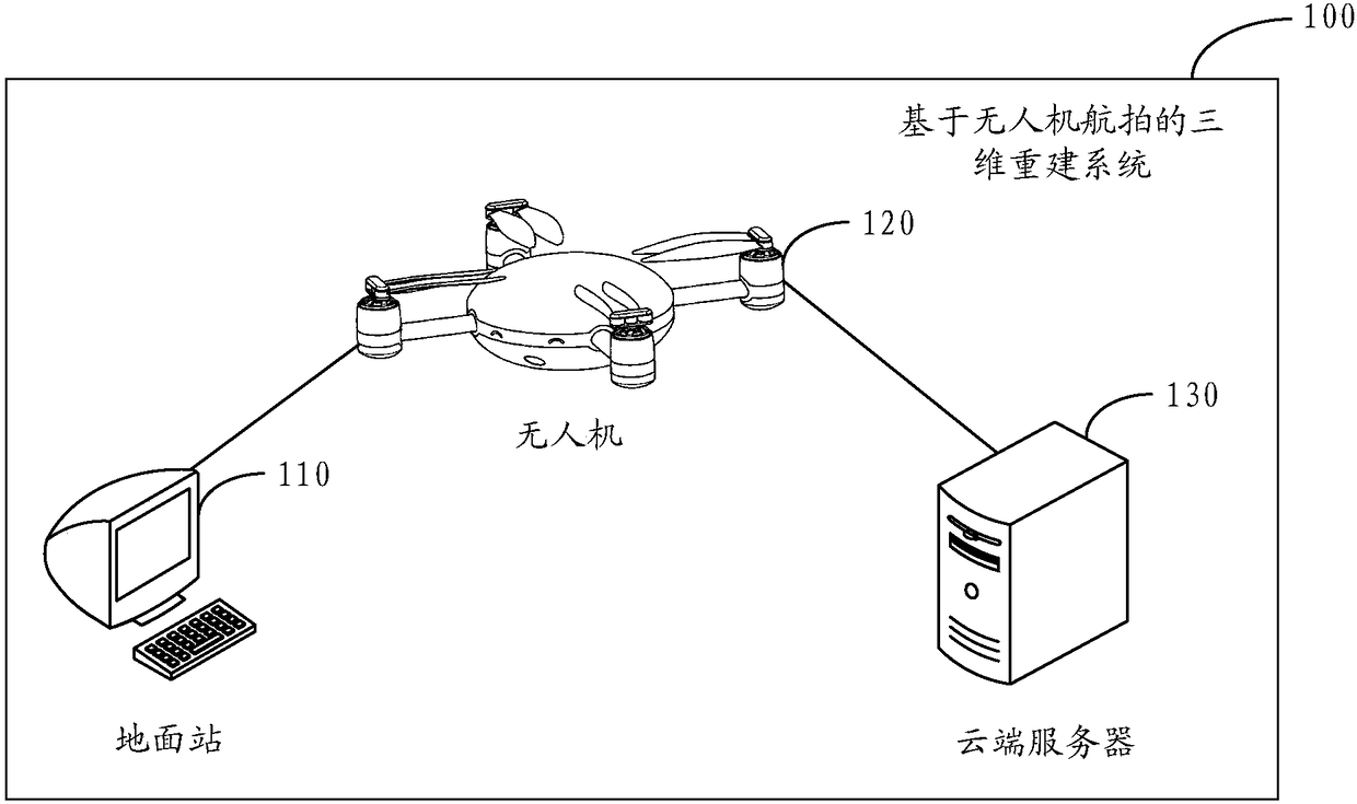
[0058] See figure 1 , is a schematic diagram of the 3D reconstruction system based on UAV aerial photography of the present invention.

[0059] exist figure 1 The illustrated system 100 includes a ground station 110, an unmanned aerial vehicle 120, and a cloud server 130. The ground station 110 is only a computer as an example. In practical applications, the ground station 110 can be smart devices such as smart phones and PADs. , the present invention is not limited to this; the UAV 120 is mounted with a shooting device ( figure 1 not shown in ), such as a camera; in addition, those skilled in the art can understand that the cloud server 130 actually refers to multiple physical servers, and among the multiple physical servers, one of them can be used as the main server, responsible for resource For deployment, the cloud server 130 has the characteristics of highly distributed and highly virtualized.

[0060] Specifically, the ground station 110 is configured to determine, b...

Embodiment 2

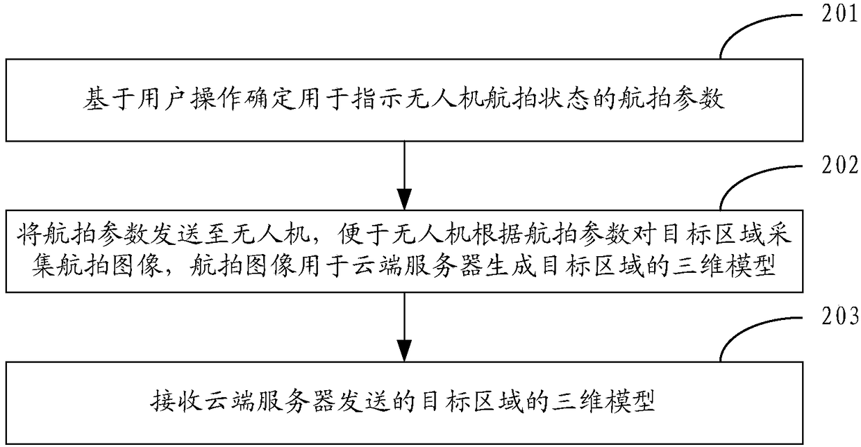
[0067] See figure 2 , is a flow chart of an embodiment of the 3D reconstruction method based on UAV aerial photography of the present invention, which is described above figure 1 Based on the example system shown, applied to figure 1 On the ground station 110 shown in the example, the following steps may be included:

[0068] Step 201: Determine aerial photography parameters for indicating the aerial photography status of the drone based on user operations.

[0069] In one embodiment, the ground station can display the satellite map to the user through the display interface, and the user can operate on the satellite map on the display interface. The surveyed area is referred to as the target area in the embodiment of the present invention for the convenience of description.

[0070] It should be noted that the manually framed area by the user may be of regular shape or irregular shape, which is not limited in the present invention.

[0071] In an embodiment, the user may ...

Embodiment 3

[0099] See Figure 4 , is a flow chart of another embodiment of the 3D reconstruction method based on UAV aerial photography of the present invention, which is described above figure 1 Based on the example system shown, applied to figure 1 On the unmanned aerial vehicle 120 shown in the example, the following steps can be included:

[0100] Step 401: Receive the aerial photography parameters sent by the ground station for indicating the aerial photography status of the UAV.

[0101] Same as the relevant description in the second embodiment above, the aerial photography parameters mentioned here may include at least one of the following: flight route, flight altitude, flight speed, shooting distance interval, and shooting time interval.

[0102] Step 402: Fly according to the aerial photography parameters and control the shooting equipment mounted on the drone to collect aerial photography images during the flight.

[0103] In the embodiment of the present invention, the UAV...


PUM


Abstract

The invention provides a three-dimensional reconstruction system based on aerial photography of unmanned aerial vehicles. The system comprises an unmanned aerial vehicle (120), a ground station (110)and a cloud server (130). The ground station is used for determining aerial photography parameters indicating the aerial photography state of the unmanned aerial vehicle, wherein the aerial photography parameters are sent to the unmanned aerial vehicle; the unmanned aerial vehicle is used for receiving the aerial photography parameters sent by the ground station and the unmanned aerial vehicle flies according to the aerial photography parameters, controls a camera mounted thereon to collect aerial photography images, and sends the aerial photography images to the cloud server; the cloud serveris used for receiving the aerial photography images and generating a three-dimensional model of a target area according to the aerial photography images. With the system, a three-dimensional model ofa target area can be obtained with high efficiency. The three-dimensional reconstruction method and device based on aerial photography of unmanned aerial vehicles are also provided.

Description

technical field [0001] The present application relates to the field of UAV technology, and in particular to a method, system and device for three-dimensional reconstruction based on UAV aerial photography. Background technique [0002] At present, by detecting the reflection of electromagnetic waves on the surface of the earth and the electromagnetic waves emitted by satellites in space, the physical information of the earth's surface can be extracted, and the information of these radio waves can be converted, and the obtained image is a satellite map. It is difficult to obtain elevation information, surface object height, slope, etc., so the application of satellite maps is very limited. Based on this, a method of establishing a three-dimensional model of the surveying and mapping area is proposed in the prior art, so as to understand the topography of the surveying and mapping area more clearly through the three-dimensional model. [0003] In one solution, the 3D model of...

Claims


Application Information

Patent Timeline
Patent Type & Authority Applications(China)
IPC IPC(8): G06T17/00
CPCG06T17/00G06T2200/08H04N5/77H04N7/185G06T17/05B64C39/022H04N23/661B64U2201/00B64U2101/30B64C39/024G06T2200/24G06T2207/10032H04N5/76H04N7/183B64U10/13B64U2201/10
Inventor 梁家斌赵开勇马岳文马东东
Owner SZ DJI TECH CO LTD
Why Eureka
Try Eureka