Fish feeding device with stirring blades
A technology of stirring blades and feeding devices, which is applied in fish farming, transportation and packaging, mixers, etc., can solve the problems of economic loss of fish farming industry, high requirements for dissolved oxygen in water, and affecting fish growth speed, etc. , to achieve the effect of improving the survival rate of breeding, simple structure and maintaining water flow
- Summary
- Abstract
- Description
- Claims
- Application Information
AI Technical Summary
Problems solved by technology
Method used
Image
Examples
Embodiment 1
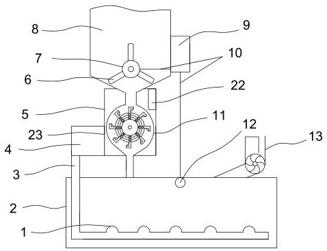
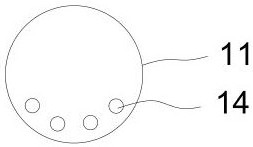
[0021] Such as Figure 1-2 As shown, the fish feeding device with stirring blades comprises a breeding box 2, and a water pipe 13 is arranged on the upper right of the breeding box 2, and the water pipe 13 is connected with a water source, and the upper end of the breeding box 2 is provided with a thermal insulation shell 5, and the thermal insulation shell 5 built-in stirring ball 11, a stirring device is provided in the stirring ball 11, the discharge port of the stirring ball 11 passes through the bottom of the heat preservation shell 5 and is connected with the breeding box 2, and the upper end of the stirring ball 11 is connected with the 8 feeding ports of the bait box. The upper end of the box is equipped with a thermal insulation shell, and the thermal insulation shell has a built-in stirring ball. The temperature in the stirring ball can always maintain a certain heat, and the bait in the stirring ball can be dried. This device has a simple structure and is easy to ope...
Embodiment 2
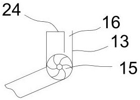
[0025] Such as image 3As shown, the optimization scheme of this embodiment on the basis of Embodiment 1 is: the water pipe 13 is bent, the water pipe 13 is bent with a water stop ball 15 stuck, and the surface of the water stop ball 15 is evenly distributed with water leakage holes, and the water stop ball 15 The inner wall of the upper water pipe 13 is connected with an L-shaped water retaining plate 24, and a water inlet 16 is formed between the L-shaped water retaining plate 24 and the water pipe 13. The ratio of the diameter of the water inlet 16 to the diameter of the water stop ball 15 is 1:3. Set the water pipe into a bent shape, and the water stop ball is stuck at the bend of the water pipe, and the surface of the water stop ball is evenly distributed with water leakage holes. A water inlet is formed between them, and the ratio of the diameter of the water inlet to the diameter of the water-stop ball is 1:3, so that when the water enters from the water pipe inlet, it ...
Embodiment 3
[0027] Such as Figure 4-6 As shown, the optimization scheme of this embodiment on the basis of Embodiment 1 is: a stirring device, including a rotating shaft 18, the surface of the rotating shaft 18 is evenly distributed with L-shaped stirring plates 17, and the L-shaped stirring plates 17 and the vertical surface of the rotating shaft 18 are uniformly arranged. Cloth is provided with through-hole 21, and the through-hole on each L-shaped stirring plate 17 is connected by net rope 19, forms the coil coaxial with rotating shaft 18, and L-shaped stirring plate 17 sides are uniformly provided with through groove 20, and through groove 20 and through-hole 21 staggered distribution. The stirring device is composed of a rotating shaft and an L-shaped stirring plate. Through holes are evenly distributed on the vertical surface of the L-shaped stirring plate and the rotating shaft, and the through holes on each L-shaped stirring plate are connected by a net rope to form a coaxial wit...
PUM
 Abstract
Description
Claims
Application Information
 - R&D
- Intellectual Property
- Life Sciences
- Materials
- Tech Scout
- Unparalleled Data Quality
- Higher Quality Content
- 60% Fewer Hallucinations
Browse by: Latest US Patents, China's latest patents, Technical Efficacy Thesaurus, Application Domain, Technology Topic, Popular Technical Reports.
© 2025 PatSnap. All rights reserved.Legal|Privacy policy|Modern Slavery Act Transparency Statement|Sitemap|About US| Contact US: help@patsnap.com


