Fixture assisting in impeller welding
An auxiliary impeller and fixture technology, applied in auxiliary welding equipment, auxiliary devices, welding equipment, etc., can solve the problems of no impeller welding auxiliary tools, high cost of automatic welding equipment, affecting the quality of the impeller, etc., to achieve ingenious structure, enhanced strength, good fixed effect effect
- Summary
- Abstract
- Description
- Claims
- Application Information
AI Technical Summary
Problems solved by technology
Method used
Image
Examples
Embodiment 1
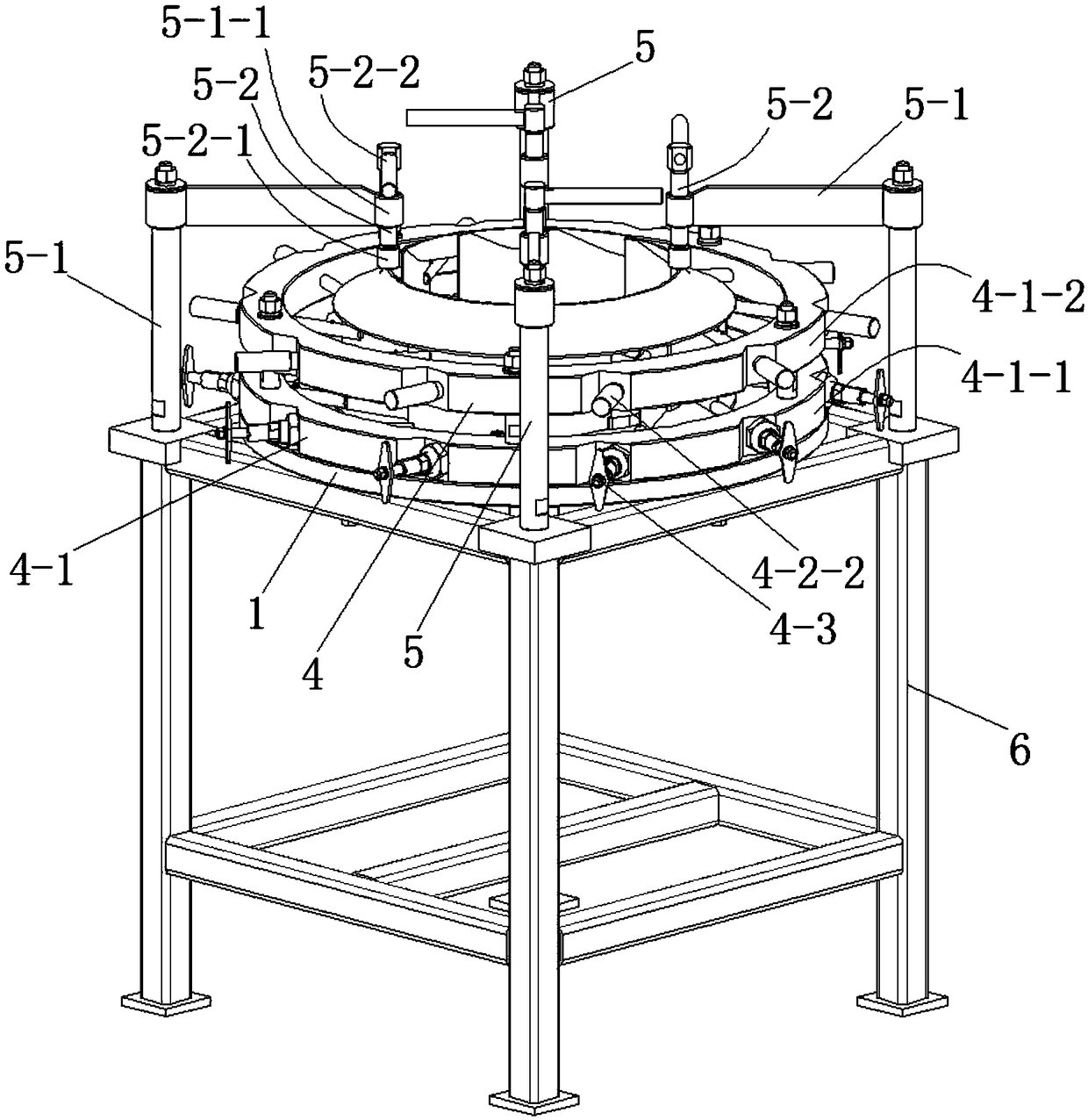
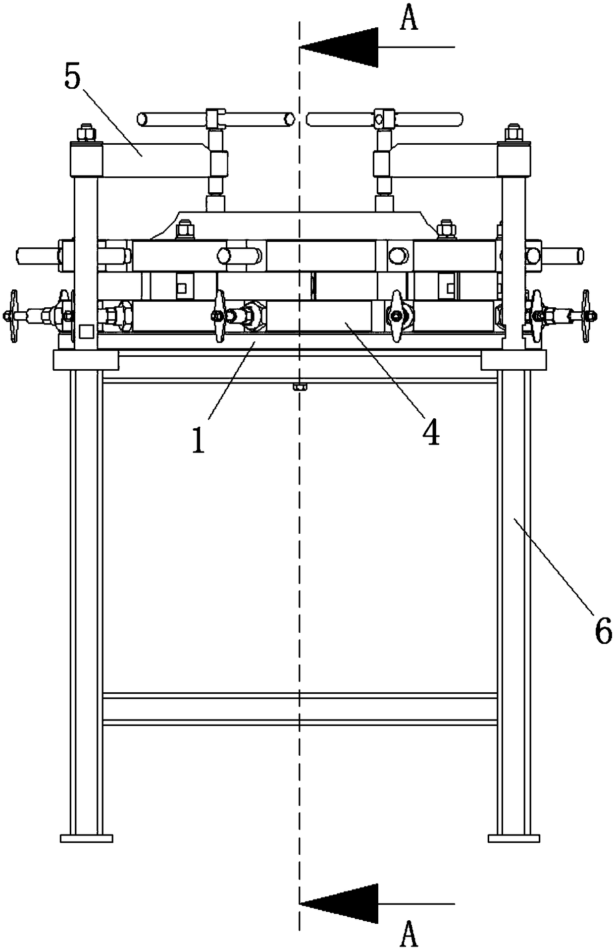
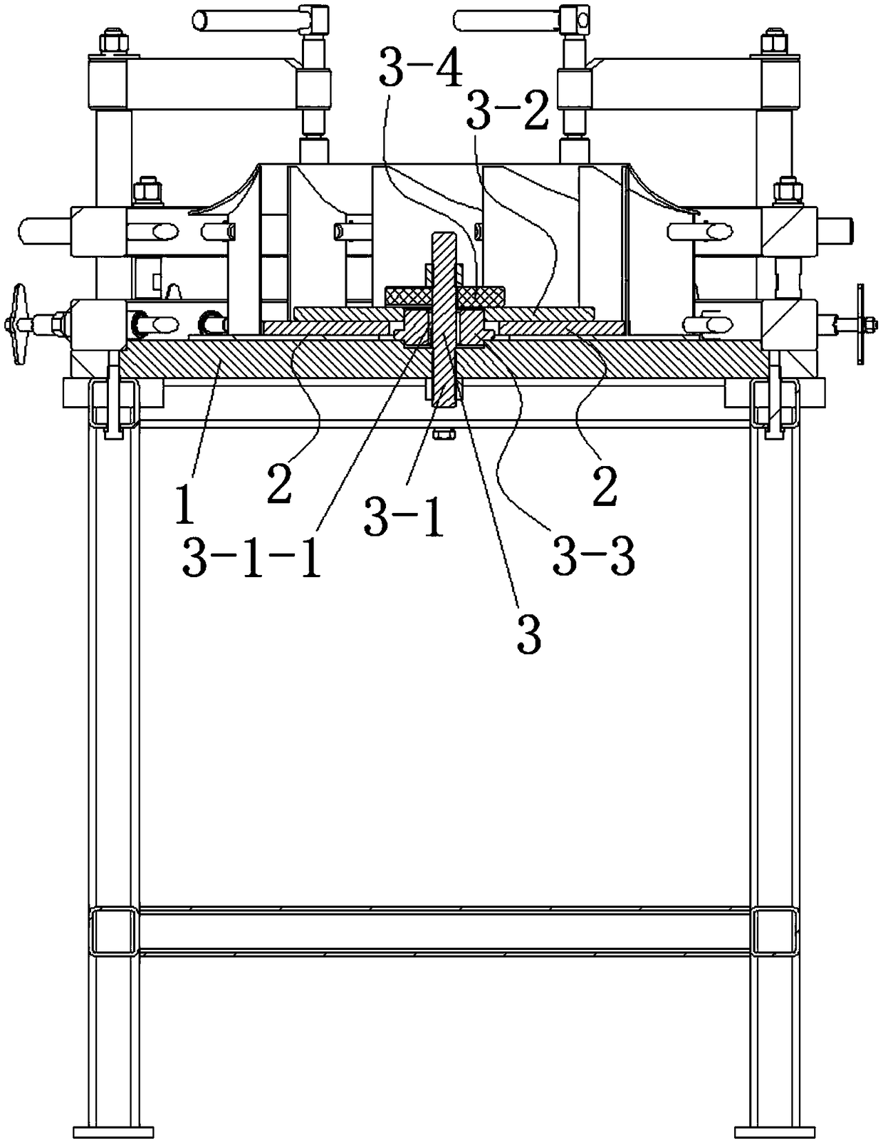
[0049] See Figure 1 to Figure 6 , the fixture for auxiliary impeller welding in this embodiment includes a base plate 1 , a positioning member 2 , a bottom plate fixing assembly 3 , a blade fixing mechanism 4 and a top plate fixing assembly 5 .
[0050]The positioning member 2 fixes the impeller bottom plate on the base plate 1 through the bottom plate fixing assembly 3 . The positioning member 2 is provided with several positioning parts for positioning the blades of the impeller. The blade fixing mechanism 4 positions each blade of the impeller. The top plate fixing assembly 5 fixes the impeller top plate on the top of the blade.
[0051] The bottom plate fixing assembly 3 includes a screw rod 3-1, a pressing plate 3-2, a fixing sleeve 3-3 and a washer 3-4. The screw rod 3 - 1 is installed on the base plate 1 . The pressing plate 3-2 is sleeved on the screw rod 3-1, and is located directly above the positioning member 2. Both the top and the bottom of the screw rod 3-1...
Embodiment 2
[0073] This embodiment is basically the same as Embodiment 1, the difference is:
[0074] The positioning assembly of the blade fixing mechanism 4 includes a first positioning rod 4-2. There are two first positioning rods 4-2. One end of a first positioning rod 4-2 penetrates the side wall of the bottom frame 4-1-1 and extends into the bottom frame 4-1-1 to be positioned with the blade of the impeller, and one end of the other first positioning rod 4-2 runs through The side wall of the top frame 4-1-2 extends into the top frame 4-1-2 to be positioned with the blade of the impeller, and the two first positioning rods 4-2 are on the same vertical plane.
[0075] Preferably, one end of the first positioning rod 4-2 of the positioning assembly of the blade fixing mechanism 4 is provided with a second slot 4-2-1 matched with the blade of the impeller.
[0076] Preferably, the other end of the first positioning rod 4-2 of the positioning assembly of the blade fixing mechanism 4 is...
Embodiment 3
[0080] This embodiment is basically the same as Embodiment 1, the difference is:
[0081] The positioning assembly of the blade fixing mechanism 4 includes a second positioning rod 4-3, a fixing sleeve 4-4 and a spring. The second positioning rod 4-3, the spring and the fixed sleeve 4-4 are all provided with two.
[0082] The two fixing sleeves 4-4 are respectively fixed on the bottom frame 4-1-1 and the top frame 4-1-2, and one ends of the two fixing sleeves 4-4 pass through the bottom frame 4-1-1 and the top frame respectively. Side walls of box 4-1-2. One end of a second positioning rod 4-3 penetrates a fixing sleeve 4-4 and extends into the bottom frame 4-1-1 to be positioned with the blade of the impeller, and one end of the other second positioning rod 4-3 passes through another fixing sleeve The barrel 4-4 stretches into the top frame 4-1-2 and is positioned with the blade of the impeller. The two springs are respectively arranged in the two fixing sleeves 4-4, and t...
PUM
 Abstract
Description
Claims
Application Information
 - R&D
- Intellectual Property
- Life Sciences
- Materials
- Tech Scout
- Unparalleled Data Quality
- Higher Quality Content
- 60% Fewer Hallucinations
Browse by: Latest US Patents, China's latest patents, Technical Efficacy Thesaurus, Application Domain, Technology Topic, Popular Technical Reports.
© 2025 PatSnap. All rights reserved.Legal|Privacy policy|Modern Slavery Act Transparency Statement|Sitemap|About US| Contact US: help@patsnap.com


