
Cooling water tank used for numerical control machining center

A cooling water tank and machining center technology, applied in metal processing equipment, metal processing mechanical parts, manufacturing tools, etc., can solve the problems of limited cooling rate of cooling liquid, affecting the reuse of cooling liquid, etc., to accelerate heat dissipation and cooling. The effect of high speed and increased heat dissipation area

Inactive Publication Date: 2018-10-26
MAANSHAN YASHIDA INTELLIGENT TECH CO LTD
View PDF0 Cites 0 Cited by
  • Summary
  • Abstract
  • Description
  • Claims
  • Application Information

AI Technical Summary

Problems solved by technology

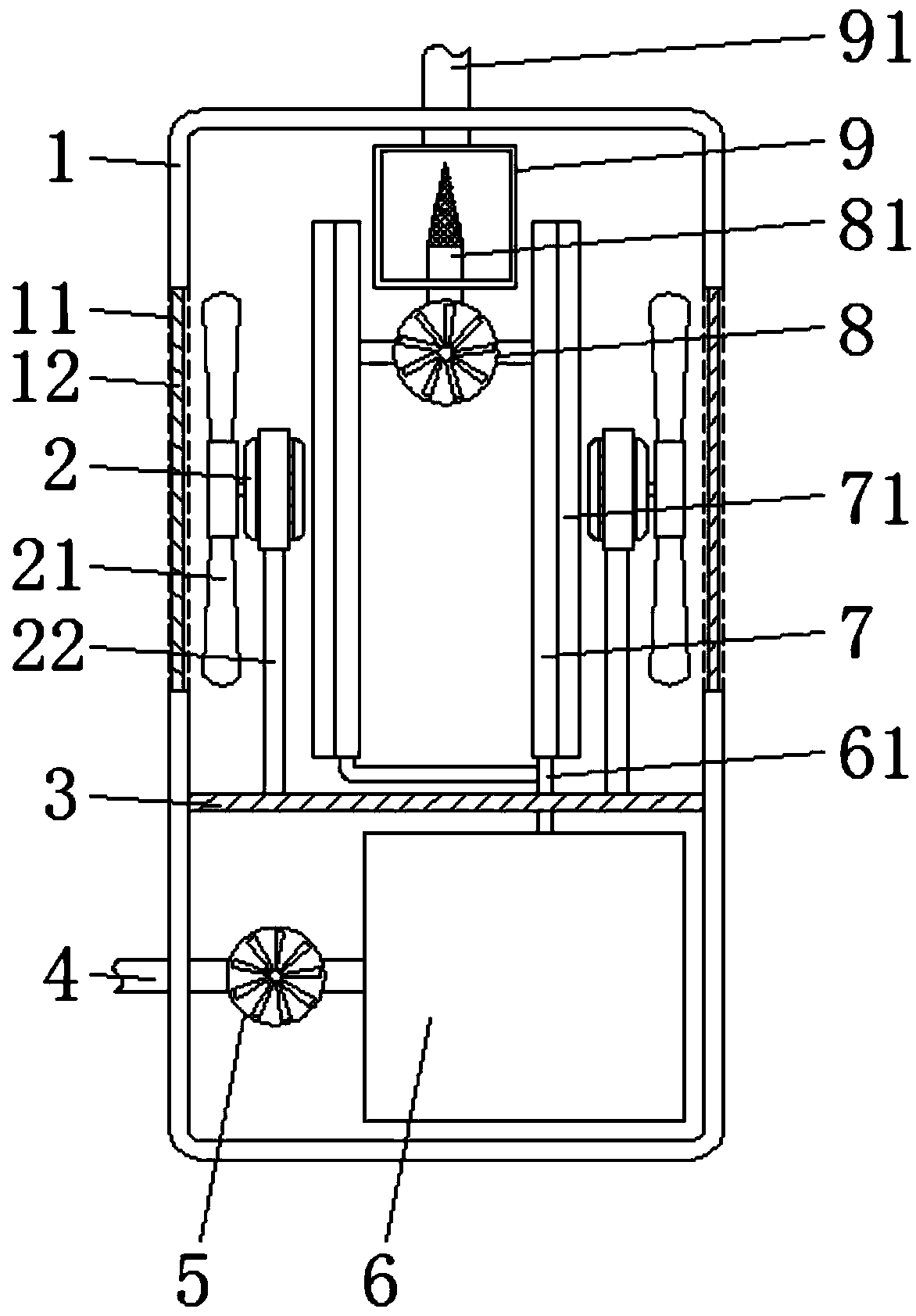
[0003] The purpose of the present invention is to provide a cooling water tank for CNC machining centers, which has the advantages of filtering workpiece debris and faster cooling rate, and solves the problems that workpiece debris affects the reuse of coolant and the cooling rate of coolant is limited

Method used


Image

  • Cooling water tank used for numerical control machining center
  • Cooling water tank used for numerical control machining center
  • Cooling water tank used for numerical control machining center

Examples


Embodiment Construction

[0019] The following will clearly and completely describe the technical solutions in the embodiments of the present invention with reference to the accompanying drawings in the embodiments of the present invention. Obviously, the described embodiments are only some, not all, embodiments of the present invention. Based on the embodiments of the present invention, all other embodiments obtained by persons of ordinary skill in the art without making creative efforts belong to the protection scope of the present invention.

[0020] In the description of the present invention, it should be noted that the terms "upper", "lower", "inner", "outer", "front end", "rear end", "both ends", "one end", "another end" The orientation or positional relationship indicated by etc. is based on the orientation or positional relationship shown in the drawings, and is only for the convenience of describing the present invention and simplifying the description, rather than indicating or implying that ...


PUM


Abstract

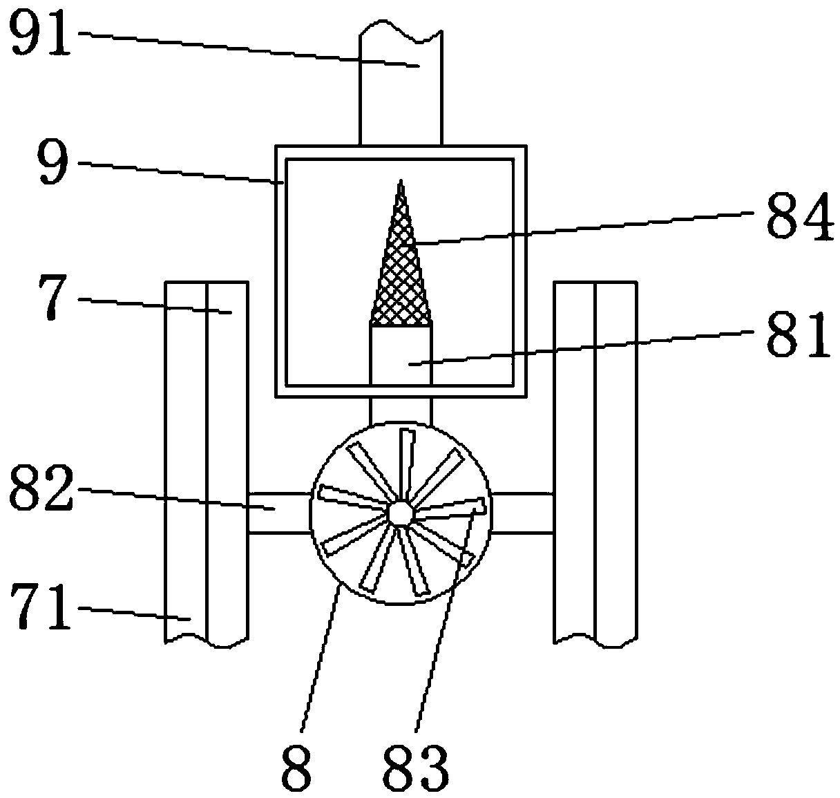
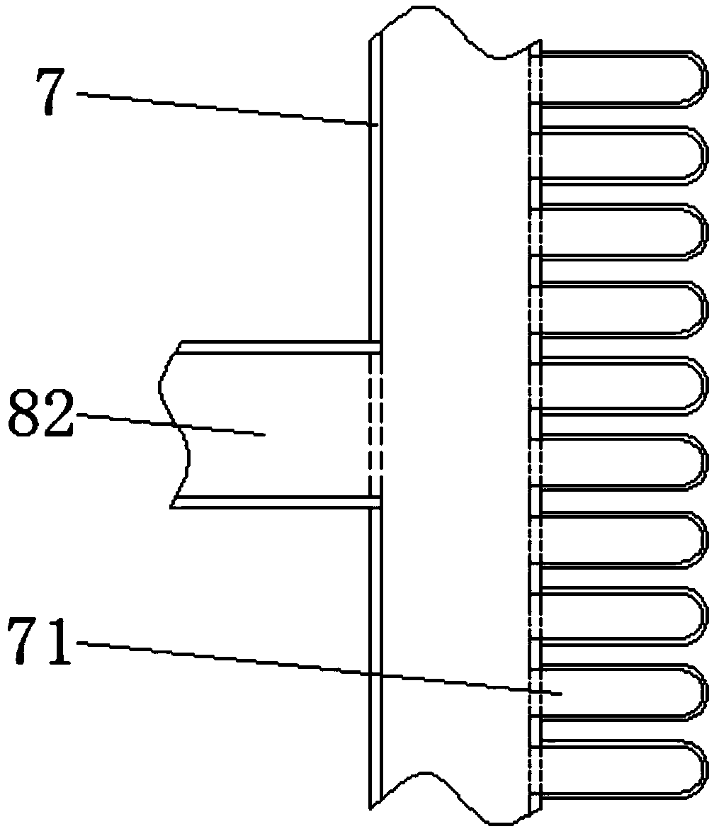
The invention discloses a cooling water tank used for a numerical control machining center. The cooling water tank comprises a shell body, an electric motor, a partition plate, heat dissipation plates, a second conveying pump and a supporting rod; the partition plate is fixedly arranged at the inner wall of the lower end of the shell body, the supporting rod is fixedly arranged on the upper surface of the partition plate, the electric motor is mounted at the upper end of the supporting rod, and the heat dissipation plates are arranged on the upper surface of the partition plate; a grid strip is arranged on the outer wall of the deviating side of each heat dissipation plate, the second conveying pump is arranged between the heat dissipation plates, and the outer walls of the two sides of the second conveying pump are connected with the inner walls of the upper ends of the heat dissipation plates through symmetrical-distributed second conveying pipes; and a collecting tank is arranged inthe upper end of the shell body, a first conveying pipe is connected with the outer wall of the upper end of the second conveying pump in an inserted mode, a filter bucket is connected with the upperend of the first conveying pipe in a sleeving mode, and a water tank body is arranged on the lower surface of the partition plate. According to the cooling water tank, the workpiece debris in the coolant is filtered out by arranging the filter bucket, the heat dissipation area of the coolant is increased through the grid strips, and the cooling speed of the coolant is increased.

Description

technical field [0001] The invention relates to the technical field of cooling water tanks, in particular to a cooling water tank for a numerically controlled machining center. Background technique [0002] CNC machining center is a high-efficiency automatic machine tool suitable for processing complex parts composed of mechanical equipment and numerical control system. CNC machining centers are currently one of the most productive and widely used CNC machine tools in the world. When the workpiece is processed inside the CNC machining center, the coolant is usually sprayed on the surface of the workpiece to avoid damage to the cutter head. After the coolant is sprayed, it can be recycled, but the coolant will be mixed with workpiece debris, which will affect the harmony of the coolant. Repeated use, and the cooling area of ​​the traditional cooling water tank is limited, the cooling rate of the cooling liquid is limited, and a good cooling effect cannot be achieved. Conte...

Claims


Application Information

Patent Timeline
Patent Type & Authority Applications(China)
IPC IPC(8): B23Q11/10
CPCB23Q11/10B23Q11/1069
Inventor 邓林海唐文超唐莉萍
Owner MAANSHAN YASHIDA INTELLIGENT TECH CO LTD
Learn More