Electric car utilizing rotation of hubs for electricity generation

A technology for electric vehicles and wheel hubs, applied in electric vehicles, electric vehicle charging technology, battery circuit devices, etc., can solve the problem of not easy long-lasting battery life, save energy and charging time, improve the level of environmental protection and energy saving, and achieve long battery life. Effect

Pending Publication Date: 2018-10-26
杭州青黛科技有限公司
View PDF6 Cites 4 Cited by
  • Summary
  • Abstract
  • Description
  • Claims
  • Application Information

AI Technical Summary

Problems solved by technology

[0003] The purpose of the present invention is to provide an electric vehicle that utilizes the rotation of the hub to generate electricity, so as to solve the problem that the existing electric vehicles are not easy to last for a long time

Method used


Image

  • Electric car utilizing rotation of hubs for electricity generation
  • Electric car utilizing rotation of hubs for electricity generation
  • Electric car utilizing rotation of hubs for electricity generation

Examples


Embodiment 1

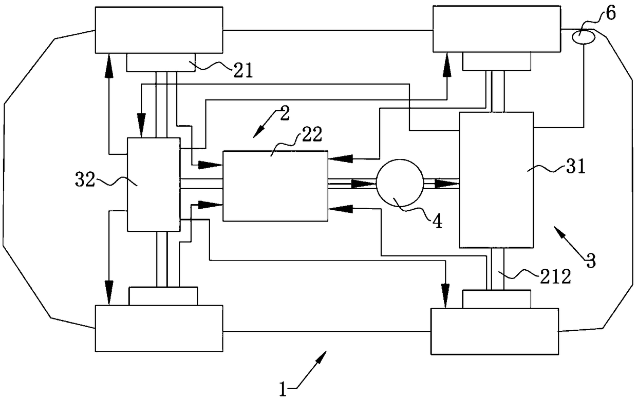
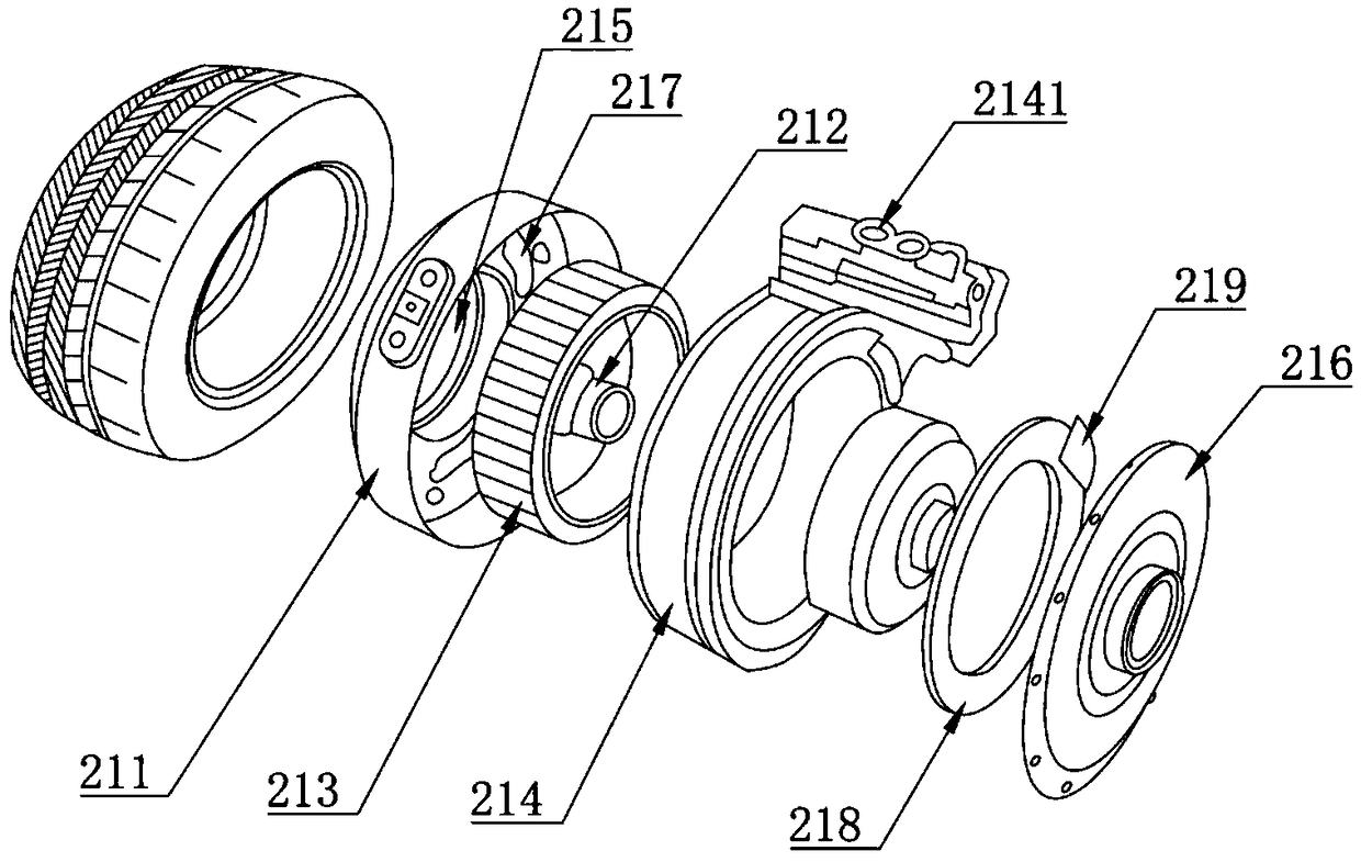
[0022] Such as figure 1 and figure 2 As shown, the present invention provides an electric vehicle that utilizes hub rotation to generate electricity, including a vehicle body 1 , a power generation device 2 and a power transmission mechanism 3 . Automobile body 1 is made up of vehicle body, chassis, tire and other various parts, and power generation device 2 comprises the hub transmission mechanism 21 that is installed on the tire of automobile body 1 and is used for the generator 22 that the mechanical energy of hub transmission mechanism 21 is converted into electric energy, and the hub Transmission mechanism 21 comprises the wheel hub 211 that is installed in the tire inner profile of automobile body 1, the bearing 212 that is used to connect the inner wheel hub 211 of tire on both sides of automobile body 1, is arranged in the wheel hub 211 and is fixed with the permanent magnet rotor 213 of bearing 212 and is arranged on The coil 214 around the permanent magnet rotor 21...

Embodiment 2

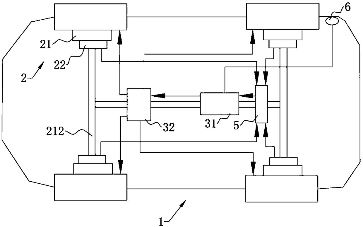
[0026] The difference from Example 1 is that the combination image 3 As shown, a generator 22 is installed at the output end of the wheel hub transmission mechanism 21 on the four tires of the automobile body 1, and a voltage stabilizer 5 is connected to the input end line of the battery pack 31, so that the voltage stabilizer 5 is connected to the four tires respectively. The generator 22 is wired for regulating the output voltage. By arranging a generator 22 on each of the four tires, it is ensured that the kinetic energy of the rotation of the automobile hub 211 is fully collected and utilized and converted into electric energy. In different running states of the car, the power generation is the same at different rotation speeds of the wheel hub 211 , and the voltage stabilizer 5 is used to ensure that the voltage output to the battery pack 31 is stable.

[0027] The electric vehicle of the present invention utilizes the power of the wheel hub 211 to drive the rotor to ro...


PUM


Abstract

The invention discloses an electric car utilizing rotation of hubs for electricity generation. The electric car comprises a car body, an electricity generating device and an electricity transmission mechanism, the electricity generating device comprises hub transmission mechanisms mounted on tyres of the car body and an electricity generator for converting mechanical energy of the hub transmissionmechanisms into electric energy, and the hub transmission mechanisms comprise the hubs mounted on the inner profiles of the tyres of the car body, bearings for being connected with the hubs in the tyres on the two sides of the car body, permanent magnet rotors arranged in the hubs and fixed to the bearings, and coils arranged on the peripheries of the permanent magnet rotors. The coils are provided with transmission line interfaces for being connected with the electricity generator, and the electricity transmission mechanism comprises a battery pack for electricity supplying and a motor for converting the electric energy into mechanical energy and driving the tyres to rotate. The electric car utilizes power generated in rotation of the hubs to drive the rotors to rotate so that the battery pack can be charged at the same time in the electricity using process, and the electric car can keep for a long duration time in running.

Description

technical field [0001] The invention relates to the technical field of electric vehicles, in particular to an electric vehicle that utilizes wheel hub rotation to generate electricity. Background technique [0002] Existing self-generating electric vehicles include electric vehicles that use solar technology to generate electricity and electric vehicles that use wind to drive fans to generate electricity. From a technical perspective, the biggest bottleneck of these two technologies is still the low energy conversion rate, which makes the power generation The power generation capacity of technology cannot meet the demand of electric vehicles for people's travel. For example, a solar car, under normal weather, the energy irradiated by the sun is 1 kilowatt per square meter. At present, the solar panel with the highest energy conversion rate is 25.6%. According to the daily power generation of a 5 square meter solar panel per car, it is less than 6 degrees. Electricity, at pr...

Claims


Application Information

Patent Timeline
Patent Type & Authority Applications(China)
IPC IPC(8): B60L11/18H02J7/14H02J7/32
CPCH02J7/1415H02J7/32B60L53/00Y02T10/70Y02T10/7072Y02T90/14
Inventor 李泓毅
Owner 杭州青黛科技有限公司
Why Eureka
Try Eureka