A heat-setting device for honeycomb porous structure cotton and its application method

A porous structure, heat-setting technology, used in heating/cooling fabrics, textiles and papermaking, fabric surface trimming, etc. High utilization rate, strong adjustability and energy saving effect

Active Publication Date: 2021-03-16
江门市江海区铁金刚机械有限公司
View PDF6 Cites 0 Cited by
  • Summary
  • Abstract
  • Description
  • Claims
  • Application Information

AI Technical Summary

Problems solved by technology

When in use, when the textile body to be dried flows through the heating system horizontally, the heating system will heat and shape the textile body. The heated area is differentially heated, and the application range is narrow

Method used


Image

  • A heat-setting device for honeycomb porous structure cotton and its application method
  • A heat-setting device for honeycomb porous structure cotton and its application method
  • A heat-setting device for honeycomb porous structure cotton and its application method

Examples


Embodiment 1

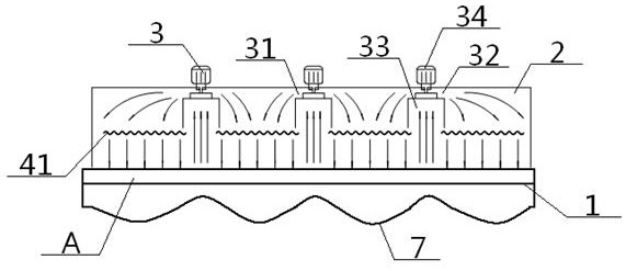
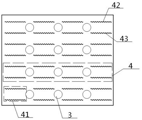
[0050] see Figure 1 to Figure 5 A heat-setting device for honeycomb porous structure cotton, comprising a plurality of fans 3; said heat-setting device comprises at least two heat-setting units 4 arranged side by side in a longitudinal direction, and the spacing between adjacent heat-setting units 4 is consistent; said The heat setting unit 4 includes heating wire groups 41 and fans 3 arranged at intervals along the transverse direction, a fan 3 is arranged between adjacent heating wire groups 41, a heating wire group 41 is arranged between adjacent fan groups 3, and a single heating Wire group 41 comprises up and down symmetrical upper heating wire 42, lower heating wire 43, upper heating wire 42, lower heating wire 43 are parallel to each other, the spacing of upper heating wire 42, lower heating wire 43 is wider than the air suction port 33 of fan 3, fan The left air outlet 31 of 3 and the heating wire group 41 on the left side of the blower fan 3 are arranged facing up an...

Embodiment 2

[0053] Basic content is the same as embodiment 1, the difference is:

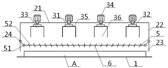
[0054] The heat-setting device also includes an air-distributing net 5, which comprises a rectangular frame 51 and a plurality of air-distributing rods 52 arranged therein. The adjacent air-distributing rods 52 are parallel to each other, and the outside of the rectangular frame 51 The drive rod 24 is flexibly connected to the inner wall of the cylindrical side plate 22, and the inner side of the rectangular frame 51 is connected to the two ends of the air-distributing rod 52. The air-distributing rod 52 is provided with a plurality of air-distributing fins 6, and the air-distributing net 5 It is located between the heating wire group 41 and the conveyor belt 1 .

[0055] When the textile body A is located at the bottom of the feeding bottom port 23, and the blowing operation and the air suction operation are continuing, the driving rod 24 drives the air-distributing net 5 to swing left and right, so as to ...

Embodiment 3

[0057] Basic content is the same as embodiment 2, the difference is:

[0058] The air equalizer rod 52 includes a plurality of pulling rods 53 arranged in sequence and has the same structure. The air equalizer sheet 6 includes an air equalizer ball 61, a movable bead 62 and a fan-shaped piece 63, and the outer surface of the air equalizer ball 61 is uniform. Four fan-shaped pieces 63 are provided, and the fan-shaped pieces 63 are perpendicular to the pulling bar 53. The inside of the uniform wind ball 61 is provided with a left bead cavity 64 and a right bead cavity 65 facing to each other. 64. A movable opening 66 is respectively opened on the opposite outer surface of the right bead cavity 65, a spherical entity 67 is formed between the left bead cavity 64 and the right bead cavity 65, and a movable opening is respectively arranged in the left bead cavity 64 and the right bead cavity 65. Bead 62, the spherical surface facing the movable opening 66 on the movable bead 62 is c...


PUM


Abstract

The invention discloses a thermal setting device of a honeycomb porous structure. The device comprises at least two thermal setting units which are arranged side by side in the longitudinal direction,the spacing of the adjacent thermal setting units is the same, the thermal setting units comprise heating wire groups and fans which are arranged in the traverse direction at intervals, a single heating wire group comprises upper and lower heating wires which are symmetric in the up-and-down direction, the upper and lower heating wires are opposite to left and right air outlets, an air suction hole is formed in the bottom of the fan, the outer body of the top of the fan penetrates through a horizontal top plate and is connected with the left and right air outlets, the periphery of the horizontal top plate is connected with the top face of a cylindrical side plate, the bottom of the cylindrical side plate is provided with a material passing bottom hole, the inner wall of the cylindrical side plate is movably connected with a uniform wind net through a driving rod, and a uniform wind rod in the uniform wind net is provided with a plurality of uniform wind pieces. According to the device, the adjustability of thermal setting is stronger, the thermal setting effect is better, the uniformity of thermal setting can be improved, the energy utilization rate is higher, and energy saving and emission reducing are achieved.

Description

technical field [0001] The invention relates to a heat-setting device for textiles, which belongs to the technical field of textiles, in particular to a heat-setting device for cotton with a honeycomb porous structure and its use method, and is particularly suitable for enhancing the adjustability of heating and setting to improve the effect of heat setting . Background technique [0002] At present, the drying equipment used in the textile field mainly includes a heating system and a cooling system connected in sequence, the heating system and the cooling system are arranged horizontally, and the heating system is located upstream of the cooling system. When in use, when the textile body to be dried flows through the heating system horizontally, the heating system will heat and shape the textile body. The heated area is differentially heated, and the application range is narrow. [0003] The disclosure of information in this background section is only intended to increase...

Claims


Application Information

Patent Timeline
Patent Type & Authority Patents(China)
IPC IPC(8): D06C7/02
CPCD06C7/02
Inventor 张智明陈博雅段耀帅姬巧玲徐巧梅顺齐肖人彬
Owner 江门市江海区铁金刚机械有限公司
Why Eureka
Try Eureka