Continuous retaining wall of deep foundation pit and construction method thereof

A construction method and technology for deep foundation pits, which are used in infrastructure engineering, excavation, artificial islands, etc., can solve problems such as bifurcation, no occlusal structure, and easy construction, so as to ensure water-stopping ability and prevent construction risks. Effect

Inactive Publication Date: 2018-10-26
江西基良工程机械设备有限公司
View PDF5 Cites 14 Cited by
  • Summary
  • Abstract
  • Description
  • Claims
  • Application Information

AI Technical Summary

Problems solved by technology

However, in the actual construction of deep foundation pits, the length of the drill bit used for drilling is relatively long. Although the initial adjustment of the vertical direction of the drill bit has been made, many factors such as mechanical vibration, human operation, topography and landform may cause the drill bit to fail in practice. During the construction process, the vertical deviation occurred, causing the pile holes to be formed obliquely instead of vertically downward from the pile holes on the surface. In the case of bifurcation, there is no overlapping part, so that the final pile body does not have an occlusal structure in the lower part, which cannot be found by the construction personnel on the surface, and can only be found after the foundation pit is dug. It is too late, it is easy to lead to the risk of construction

Method used


Image

  • Continuous retaining wall of deep foundation pit and construction method thereof
  • Continuous retaining wall of deep foundation pit and construction method thereof
  • Continuous retaining wall of deep foundation pit and construction method thereof

Examples


Embodiment 1

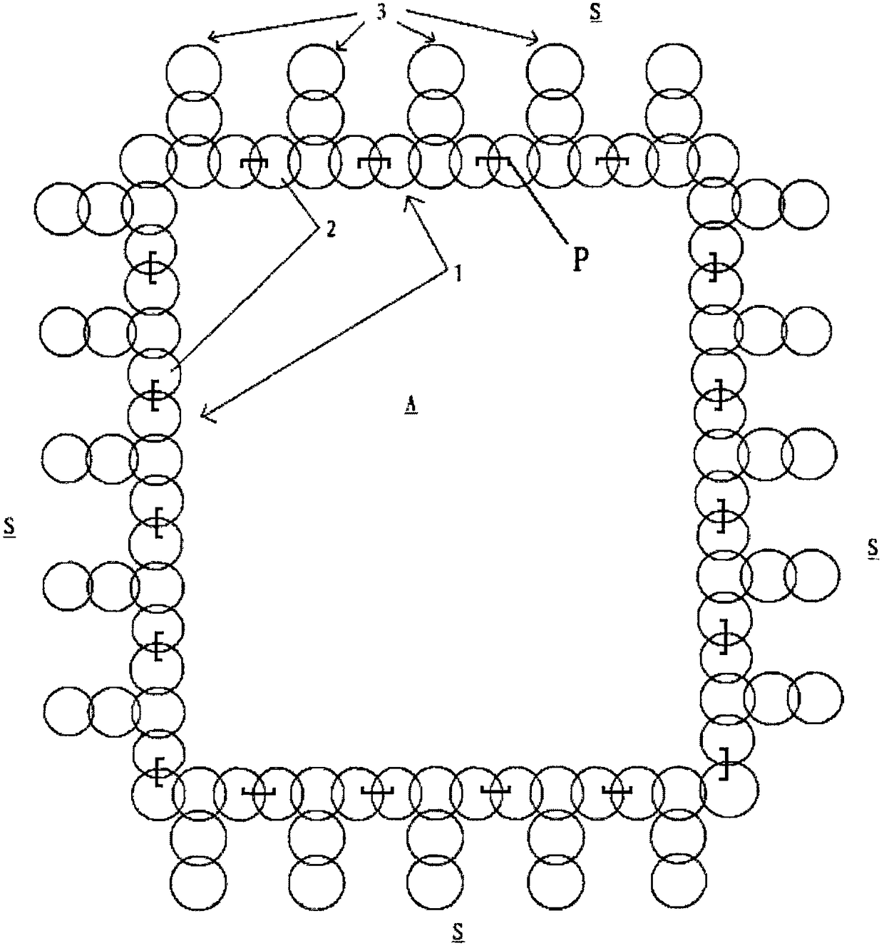
[0036] Such as figure 1 The shown continuous retaining wall of a deep foundation pit includes: a continuous occlusal part 1, which is composed of a layer of piles 2 continuously interlocked with each other, and is arranged in a ring around the foundation pit A; it also includes a water-blocking part P, which is inserted longitudinally in the The occlusion of adjacently arranged piles is arranged along the longitudinal extension of the entire pile (such as Figure 5 shown), used to prevent groundwater from penetrating from the outside of the foundation pit to the inside of the foundation pit of the continuous occlusal part. The continuous retaining wall of the deep foundation pit can also be formed by interlocking two layers of pile bodies (not shown here). Wherein, the pile body may be a cement-soil pile body, a concrete pile body, or a combination of a concrete pile body and a cement body pile body. In addition, the water-blocking component can be a water-stop plate, and ca...

Embodiment 2

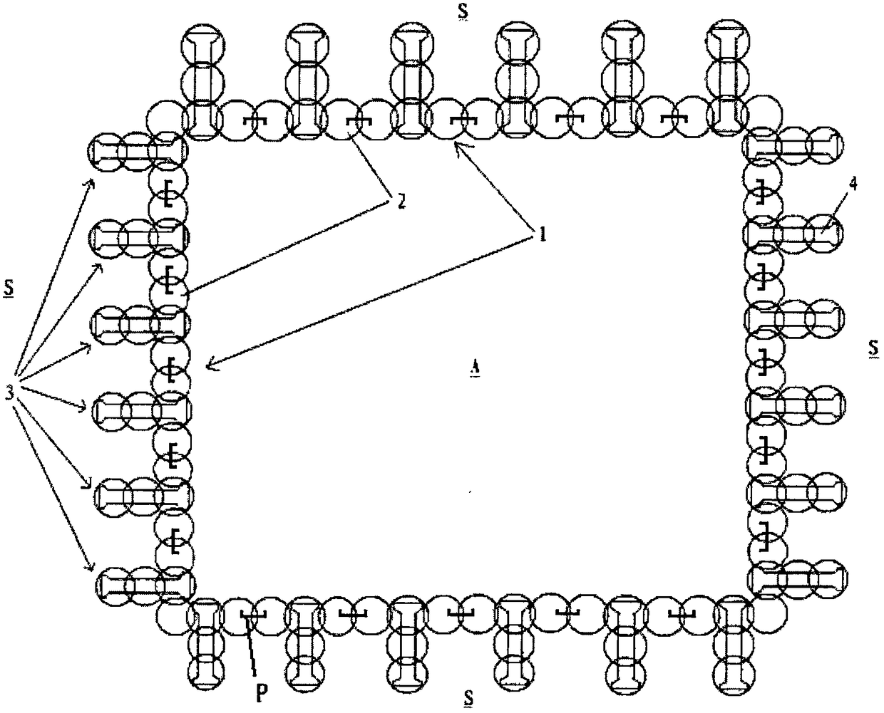
[0038] Such as figure 2 As shown, a continuous retaining wall for a deep foundation pit includes: a continuous occlusal part 1, which is composed of a layer of cement-soil piles 2 that are continuously interlocked with each other; and is annularly arranged around the foundation pit A; it also includes a water-blocking part P inserted longitudinally It is arranged at the occlusion of adjacently arranged piles, and is used to prevent groundwater from penetrating from the outside of the foundation pit of the continuous occlusion to the inside of the foundation pit; it also includes several protrusions 3, from the foundation pit A to the side of the soil S Arranged in an extended direction, each of the protrusions is composed of at least two cement-soil piles 2 that interlock with each other, wherein the protrusions 3 engage with the cement-soil piles 2 arranged at intervals in the continuous joint 1 . The continuous retaining wall of the deep foundation pit of the present embodi...

Embodiment 3

[0040] Such as image 3 The continuous retaining wall of the deep foundation pit shown, wherein, the difference between this embodiment and embodiment 2 is that each cement-soil pile body 2 in the protrusion 3 and the continuous engagement with the protrusion 3 At least one prefabricated sheet pile 4 or at least one section steel (not shown) is longitudinally inserted in the cement-soil pile body 2 in the part 1 . The prefabricated sheet pile is an I-type sheet pile (such as image 3 As shown), it can also be T-shaped sheet pile or I-shaped sheet pile; when the inserted section steel is I-shaped steel, it can also be T-shaped steel or I-shaped steel. For not yet out.

[0041] As a preferred embodiment, such as Figure 4 As shown, the continuous retaining wall of the deep foundation pit may also include: a rigid connection structure 5, which is arranged on the top of the prefabricated sheet pile 4, so as to form an integral rigid connection with the prefabricated sheet pile....


PUM


Abstract

The invention provides a continuous retaining wall of a deep foundation pit. The continuous retaining wall comprises a continuous engaged part and a water blocking component, wherein the continuous engaged part is formed in a way that at least one layer of pile bodies are continuously engaged with each other and are circularly arranged around the foundation pit; the water blocking component is longitudinally inserted into the engaged position of at least two adjacent pile bodies and is used for preventing underground water from permeating from the outer side of the foundation pit to the innerside of the foundation pit of the continuous engaged part; and the water blocking component is made of channel steel or a steel plate. According to the structure, the underground water can be effectively prevented from permeating from the engaged position of the two adjacent pile bodies into the foundation pit by the water blocking component, so that the water blocking capability of the continuousretaining wall of the deep foundation pit is increased. The invention further provides a construction method of the continuous retaining wall of the deep foundation pit.

Description

technical field [0001] The invention relates to a foundation treatment method, in particular to a deep foundation pit continuous retaining wall and a construction method thereof. Background technique [0002] In order to stop water in deep foundation pits in the prior art, several interlocking water-stop piles are usually arranged along the wall of the foundation pit to form a retaining wall with water-stop function. In order to save costs, the water-stop piles are usually Cement-soil piles are used. However, the cement-soil piles are not strong enough to retain soil. In order to solve this technical problem, those skilled in the art usually arrange the concrete piles in the inner or outer layers of the cement-soil piles, or space them with the cement-soil piles. Arranging the concrete piles makes the cement-soil piles and the concrete piles form a bite, although the effect of retaining soil and water can be achieved, and the construction cost can be effectively reduced. H...

Claims


Application Information

Patent Timeline
Patent Type & Authority Applications(China)
IPC IPC(8): E02D17/04E02D29/02
CPCE02D17/04E02D29/02
Inventor 江守慈刘献刚梁毅刘斌屈峰张东海
Owner 江西基良工程机械设备有限公司
Why Eureka
Try Eureka