A prefabricated frame structure suitable for high erosion environments such as salt lake areas

A frame structure and prefabricated technology, used in building components, building structures, buildings, etc., can solve the problems of short service life, poor durability, low corrosion resistance and ion corrosion resistance, and achieve the effect of improving service life.

Active Publication Date: 2020-10-02
HARBIN INST OF TECH
View PDF10 Cites 0 Cited by
  • Summary
  • Abstract
  • Description
  • Claims
  • Application Information

AI Technical Summary

Problems solved by technology

[0004] The purpose of the present invention is to solve the problems of ordinary reinforced concrete structures in highly erosive environments such as salt lake areas with low corrosion resistance to ion erosion, poor durability, and short service life, and to provide a prefabricated structure suitable for high erosive environments such as salt lake areas. Framework

Method used


Image

  • A prefabricated frame structure suitable for high erosion environments such as salt lake areas
  • A prefabricated frame structure suitable for high erosion environments such as salt lake areas
  • A prefabricated frame structure suitable for high erosion environments such as salt lake areas

Examples


specific Embodiment approach 1

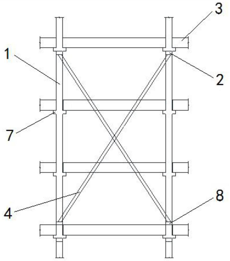
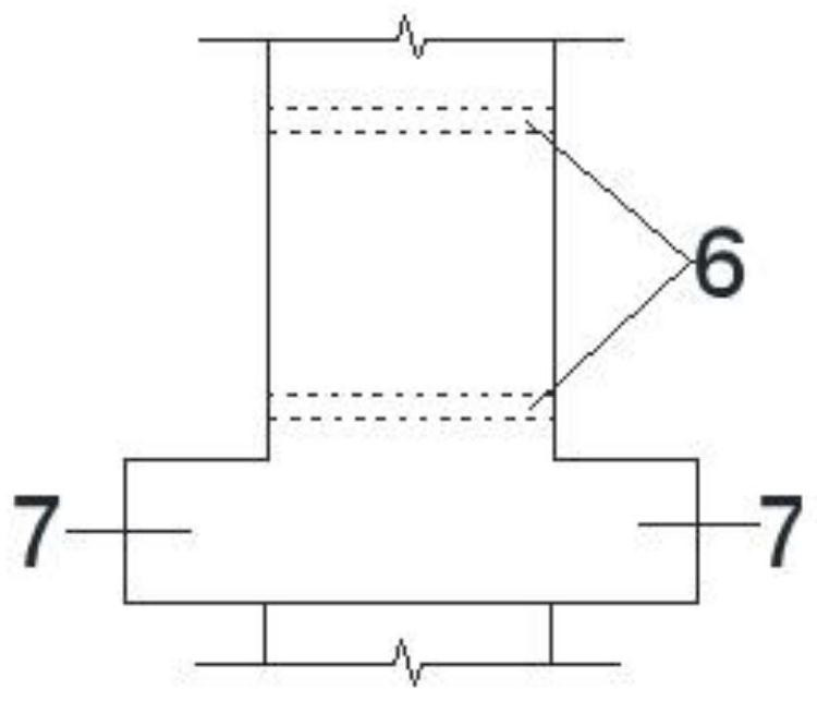
[0016] Specific implementation mode one: combine figure 1 , figure 2 , image 3 , Figure 6 and Figure 7 Describe this embodiment. In this embodiment, a prefabricated frame structure suitable for high erosion environments such as salt lake areas uses UHPC solid columns 1 as frame columns, UHPC closed cavity beams 3 as frame beams, and UHPC struts 4 as inter-column columns. The lateral supports are connected; the UHPC solid column 1 is provided with a corbel 7 at each floor height for supporting the UHPC closed cavity beam 3, and the lower end of the uppermost corbel 7 on the UHPC solid column 1 is provided with The upper bump 2, the upper end of the lowermost corbel 7 on the UHPC solid column 1 is provided with a lower bump 8, and the upper bump 2 and the lower bump 8 are provided with a bump reserved for fixing the UHPC strut 4 In the channel 9 , two UHPC struts 4 are intersected and arranged between four UHPC solid columns 1 .

[0017] The height of the corbel is set ...

specific Embodiment approach 2

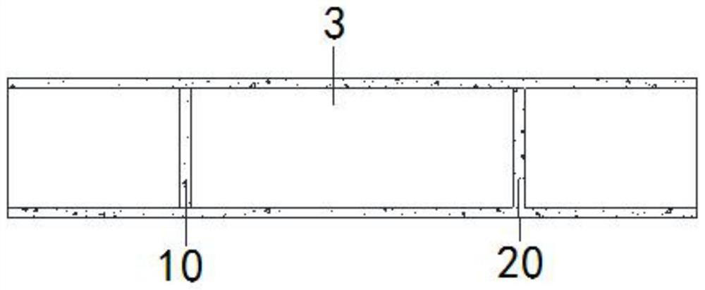
[0019] Specific implementation mode two: combination Figure 4 and Figure 5 This embodiment is described. The difference between this embodiment and specific embodiment 1 is that the UHPC closed cavity beam 3 is prepared according to the following steps: the cavity beam 5 is manufactured by the long-line platform extrusion molding process; the cavity beam 5 is placed on the lifting platform base 14 along the beam length direction; adjust the height of the lifting platform top plate 11, so that the length of the lifting platform top plate 11 from the upper end of the cavity beam 5 meets the anchorage length of the connecting rib 15 on the cavity beam 5, and then in the cavity Pour the first transverse partition 10 in the cavity beam 5; adjust the height of the lifting platform top plate 11 so that the length of the lifting platform top plate 11 from the lower end of the cavity beam 5 meets the anchorage length of the connecting rib 15 in the closed cavity beam 5, and then pass...

specific Embodiment approach 3

[0020] Embodiment 3: The difference between this embodiment and Embodiment 1 or 2 is that the connection between UHPC solid columns 1 and UHPC struts 4 is carried out according to the following steps: two UHPC struts 4 are cross-placed on four UHPC solid columns 1, pass the prestressed connecting rib 17 out of the reserved hole 9 in the lower bump 8 and then extend into the reserved hole 16 in the UHPC strut 4, and then pass through the UHPC strut 4 The reserved channel 16 of the support rod penetrates into the reserved channel 9 of the bump in the upper bump 2, and the two ends of the prestressed connecting rib 17 withstand the backing plate 18, and the prestressed connecting rib 17 is tensioned and anchored by an anchor 19 , after the prestressed connecting rib 17 is anchored, the anchor is sealed with epoxy resin mortar, that is, the connection between the UHPC solid column 1 and the UHPC strut 4 is completed. Others are the same as those in Embodiment 1 or 2.


PUM


Abstract

The invention relates to an assembled frame structure suitable for salt lake areas and other high erosion environments. To solve the problem that common reinforced concrete structures, in salt lake areas and other high erosion environments, have low resistance to corrosive ion erosion, poor in durability and short in service life, a novel assembled frame structure system is provided which uses small-section UHPC (ultrahigh performance concrete) solid columns as frame columns to bear vertical load, extruded UHPC closed cavity beams as frame beams, and prestress-restrained UHPC brace as inter-column lateral braces to bear horizontal seismic action and effectively dissipate energy. The assembled frame structure is applicable to salt lake areas and other high erosion environments.

Description

technical field [0001] The invention relates to an assembled frame structure. Background technique [0002] my country is a country with many salt lakes, with more than 1,500 salt lakes and a total area of ​​50,000 square kilometers. In the environment of the salt lake area, ordinary reinforced concrete structures will have different degrees of cracking, pan-alkali, and steel corrosion in a short period of time after completion. Corrosion and other problems cause serious damage to the structure, making it impossible to use normally and seriously affecting the service life of the structure. [0003] Ultra-high performance concrete (UHPC) enhances the mechanical properties and durability of materials by increasing the fineness and activity of components, improving the internal pore structure and reducing porosity. Therefore, UHPC is used in engineering construction in highly erosive environments such as salt lake areas, which can well resist the erosion of harmful ions such ...

Claims


Application Information

Patent Timeline
Patent Type & Authority Patents(China)
IPC IPC(8): E04B1/20E04B1/21E04B1/64
CPCE04B1/20E04B1/21E04B1/642
Inventor 郑文忠常卫王英
Owner HARBIN INST OF TECH
Why Eureka
Try Eureka