
Mechanized upward segmental recovery method

A segmented line and segmented blasting technology, which is applied in surface mining, earthwork drilling, underground mining, etc., can solve the problems of hidden safety hazards, short distances, and high space, so as to ensure the blasting effect, reduce hidden dangers, and improve the distribution The effect of hole efficiency

Active Publication Date: 2018-10-26
深圳市中金岭南有色金属股份有限公司凡口铅锌矿 +1
View PDF8 Cites 3 Cited by
  • Summary
  • Abstract
  • Description
  • Claims
  • Application Information

AI Technical Summary

Problems solved by technology

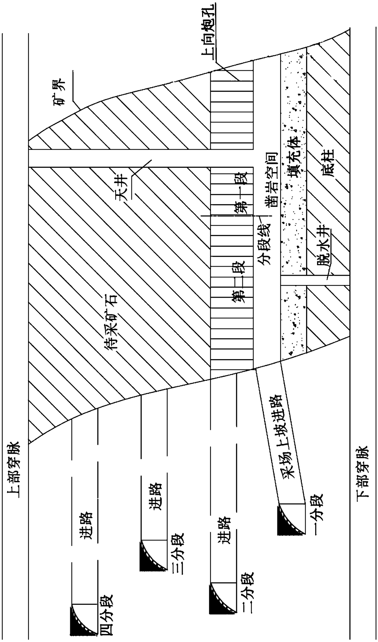
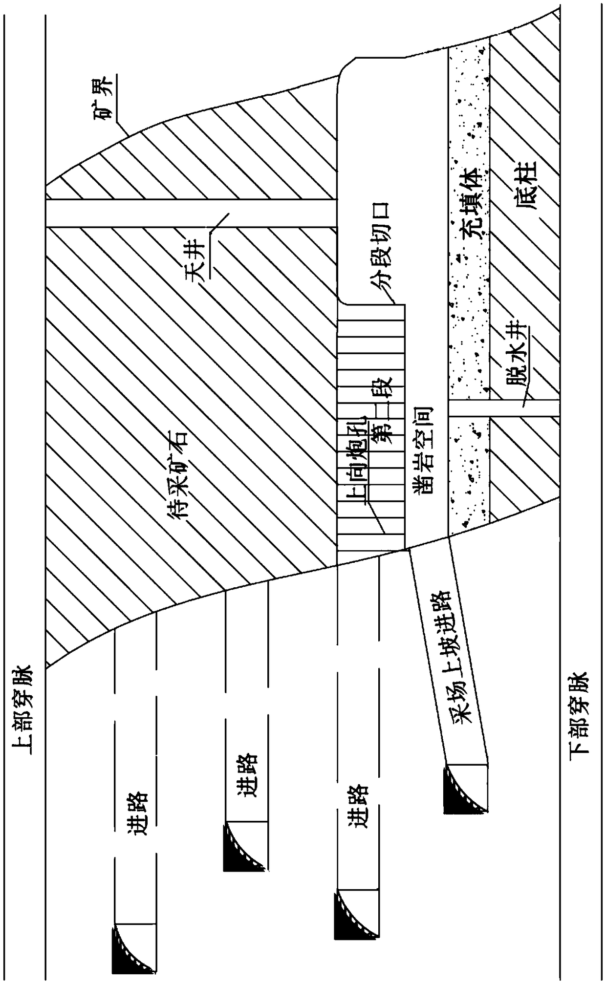
[0004] Yet there are following two problems in above-mentioned conventional subsection mining method; One, as image 3 As shown, there are many turquoise rocks produced at the segmental incisions formed by the first stage blasting, and because of the high space and the inability to reversely process the turquoise rocks, there is a great safety hazard when shoveling out the ore dropped by the first stage blasting due to the falling of the turquoise rocks; 2. The distance between the blasting position of the second stage and the section cut is short, and there are serious safety hazards in the blasting operation of the second stage

Method used


Image

  • Mechanized upward segmental recovery method
  • Mechanized upward segmental recovery method
  • Mechanized upward segmental recovery method

Examples


Embodiment Construction

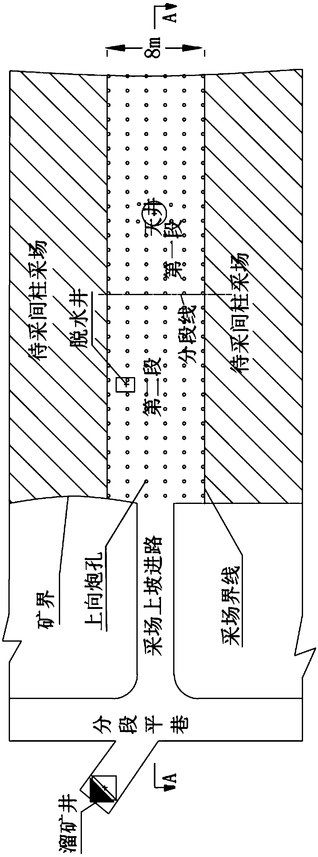
[0033] Please also see Figure 4 with Figure 5 , Figure 4 It is the plan view of blast hole opening layout before the first section blasting of the recovery method of the present invention, Figure 5 for Figure 4 B-B longitudinal section view.

[0034] Using the high-layer mechanized upward mining method of the present invention to recover a stope with a length exceeding 50m, specifically comprises the following steps:

[0035] (1) Stope segmentation:

[0036] According to the length direction of the stope, the stope is divided into the first section and the second section from the inside to the outside, and a segment line is drawn between the first section and the second section. The first section is far from the stope approach, and the second section is closer to the stope approach.

[0037] (2) Blast hole layout:

[0038] The 0th row of blastholes is arranged along the section line of the stope, and the -1st row, the -2nd row, ..., the No. -i row of gun holes, i ...


PUM

PropertyMeasurementUnit
Lengthaaaaaaaaaa
Heightaaaaaaaaaa

Abstract

The invention relates to a mechanized upward segmental recovery method. The recovery method includes the following steps of (1) conducting segmentation on a recovery field; (2) conducting arrangementof blast holes, wherein the 0-th row of blast holes are distributed along a segmentation line of the recovery field, the -1-th row, -2-th row...and -i-th row of blast holes and the 1-st row, 2-nd row...and n-th row of blast holes are sequentially distributed in a first segment and a second segment respectively in the direction away from the 0-th row of blast holes, the orifices of the 0-th row ofblast holes are positioned in the segmentation line, the array pitch between the 0-th row and the orifices of the -1-th row of blast holes is 1.4 m, the array pitch between the 0-th row and the orifice bottoms of the -1-th row of blast holes is 0.8 m, the array pitch between the 1-st row and the orifices of the 0-th row of blast holes is 2.3 m, the array pitch between the 1-st row and the orificebottoms of the 0-th row of blast holes is 1.4 m, the array pitch between the 2-nd row and the orifices of the 1-st row of blast holes is 0.5 m, the array pitch between the 2-nd row and the orifice bottoms of the 1-st row of blast holes is 1.5 m, the array pitch between the 3-rd row and the orifices of the 2-nd row of blast holes is 1.0 m, the array pitch between the 3-rd row and the orifice bottoms of the 2-nd row of blast holes is 1.5 m, the -1-th row, -2-th row and -i-th row of blast holes and the 3-rd row, 4-th row and n-th row of blast holes are all vertical blast holes facing upwards, andthe array pitch of these rows is 1.4 m; (3) conducting segmental blasting for discharging ore. The recovery method has the advantages that the safety is high, the recovery effect is great, and damageof the ore is small.

Description

technical field [0001] The invention relates to the technical field of mining, in particular to a mechanized upward segmental mining method. Background technique [0002] At present, mines widely adopt the mechanized up-to-middle-deep hole layered filling mining method. Segmented mining is to first recover a section away from the far end of the approach, and then recover a section near the end. For a mine stope with a width of 8m and a length of more than 50m, it is often necessary to divide the stope into two sections from the inside to the outside, and then use The trolley with a width of 8m is used for mining in sections, and for stopes with a length of more than 70m, it may even be necessary to divide the stope into three sections from the inside to the outside for mining. Segmented mining can reduce the amount of primary explosives, thereby reducing blasting vibration damage, improving safety, facilitating remote operation of shoveling and reducing losses. [0003] se...

Claims


Application Information

Patent Timeline
IPC IPC(8): E21C41/16
CPCE21C41/16
Inventor 钟杰黄沛生史秀志谢胜许春胜曾辉林
Owner 深圳市中金岭南有色金属股份有限公司凡口铅锌矿
Learn More