Main machine structure of simulation test machine for evaluating blockage ratio of electronically-controlled oil injector of gasoline engine

A simulation test, electronically controlled fuel injection technology, applied in the testing of machine/structural components, engine testing, machine/engine, etc., can solve the problem that the bench test does not have fast, online detection, time-consuming, and cannot express electronically controlled injection. Problems such as the state of deposits on the needle valve of the oiler

Active Publication Date: 2018-10-26
BEIJING CHAOYANG GAOKE APPLIED TECH RES INST CO LTD
View PDF6 Cites 5 Cited by
  • Summary
  • Abstract
  • Description
  • Claims
  • Application Information

AI Technical Summary

Problems solved by technology

Bench testing equipment is expensive and time-consuming; therefore, bench testing does not have the technical advantage of rapid, on-line testing
The other is the gasoline engine intake valve deposit simulation test machine, which simulates the deposition process of the deposits at the intake valve of the gasoline engine and the cleaning performance after adding gasoline detergent; The detergency of the cleaning performance does not indicate the state of deposits in the needle valve part of the electronically controlled injector

Method used


Image

  • Main machine structure of simulation test machine for evaluating blockage ratio of electronically-controlled oil injector of gasoline engine
  • Main machine structure of simulation test machine for evaluating blockage ratio of electronically-controlled oil injector of gasoline engine
  • Main machine structure of simulation test machine for evaluating blockage ratio of electronically-controlled oil injector of gasoline engine

Examples


Embodiment Construction

[0055] According to the following detailed description of specific embodiments of the application in conjunction with the accompanying drawings, those skilled in the art will be more aware of the above and other objectives, advantages and features of the application.

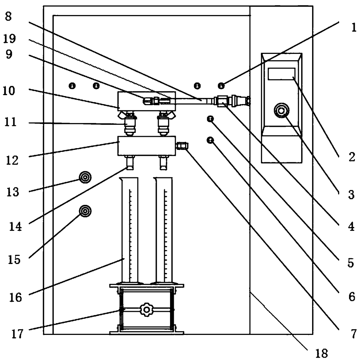
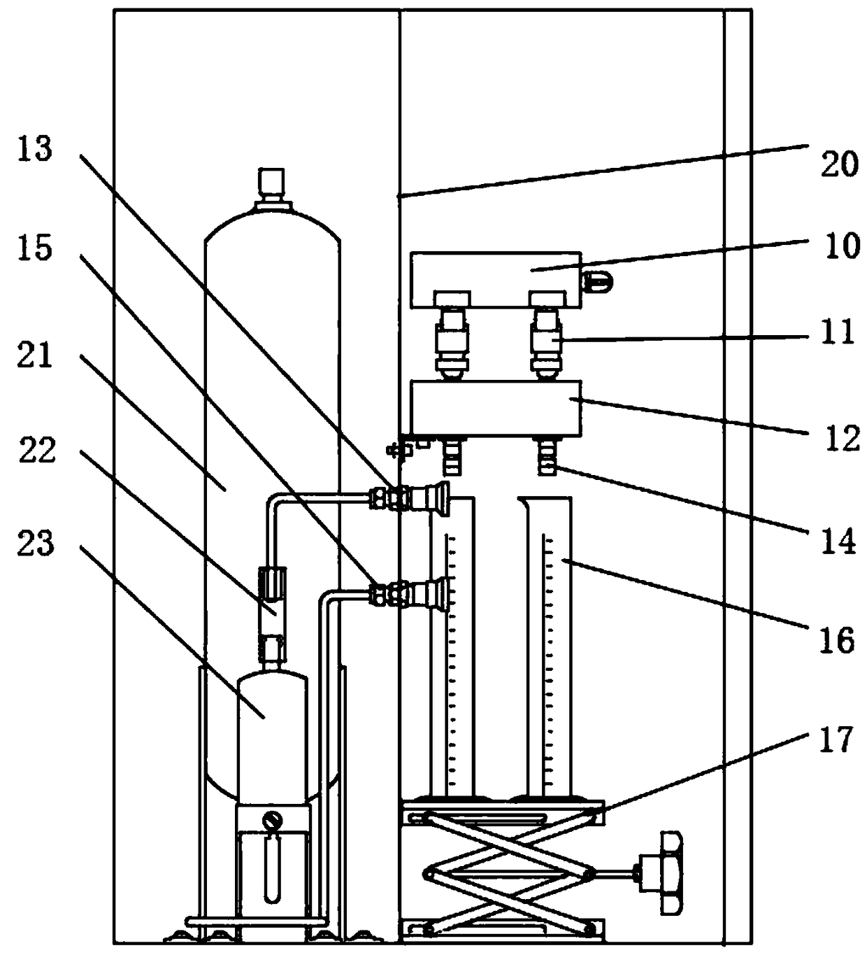
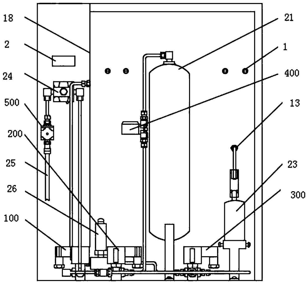
[0056] Figure 1 to Figure 3 One embodiment of the simulated test device of the present application is shown. This embodiment discloses a simulation test device for testing at least one electronically controlled fuel injector 11 . The simulation test device includes: a nitrogen pressure regulating device, a fuel storage device 21, a fuel distributor 10, a heating block 12 and a measuring device.

[0057] Wherein, the fuel storage device 21 is connected with the nitrogen pressure regulating device; the fuel distributor 10 communicates with the fuel storage device 21, and the lower end surface of the fuel distributor 10 is also connected with the electronic control injector 11 The heating device is used to heat ...


PUM


Abstract

The invention discloses a main machine structure of a simulation test machine for evaluating the blocking ratio of the electronically-controlled oil injector of a gasoline engine. A simulation test device is used for detecting at least one electronically-controlled oil injector and comprises a nitrogen pressure regulating device, a fuel oil storage device, a fuel oil distributor, a heating deviceand a measuring device, wherein the fuel oil storage device is connected with the nitrogen pressure regulating device; the fuel oil distributor is communicated with the fuel oil storage device; the lower end surface of the fuel oil distributor is connected with the electronically-controlled oil injector; the heating device is used for heating a needle valve part of the electronically-controlled oil injector and measuring the temperature of the electronically-controlled oil injector; and the measuring device is arranged below the electronically-controlled oil injector and used for accommodatinga liquid injected from the electronically-controlled oil injector and measuring the amount of the liquid. Through the adoption of the simulation test device, the blockage tendency of the electronically-controlled oil injector can be judged by measuring the amount of the liquid flowing out from the electronically-controlled oil injector, thereby realizing long-time automatic detection on the electronically-controlled oil injector. The simulation test device can be filled with gasoline or a cleaning fluid, so that multiple functions are achieved.

Description

technical field [0001] The present application relates to the technical field of test equipment, in particular to a simulation test device for detecting at least one electronically controlled fuel injector, and more specifically, to a simulation for evaluating the clogging tendency of an electronically controlled fuel injector Test machine host structure. Background technique [0002] The electronically controlled fuel injectors of gasoline engines, also called fuel nozzles, tend to form deposits at the tip, which restricts the uniform injection of fuel, thus causing problems of reduced fuel efficiency and increased emissions of pollutants. With the continuous improvement of gasoline engine manufacturing technology, more and more in-cylinder direct injection engines on the market have replaced old-fashioned engines. Due to changes in its structure, it also directly affects the formation and distribution of carbon deposits inside the engine. Therefore, detecting the clogging...

Claims


Application Information

Patent Timeline
Patent Type & Authority Applications(China)
IPC IPC(8): F02M65/00
CPCF02M65/00F02M65/001F02M65/008
Inventor 黄博涛邓宇徐立国
Owner BEIJING CHAOYANG GAOKE APPLIED TECH RES INST CO LTD
Why Eureka
Try Eureka